DC Charging Station or DC EVSE: Functional Overview
This article focuses solely on unidirectional DC EVSEs and does not cover Bidirectional DC EVSEs.
What is DC EVSE?
DC EVSE refers to charging stations that deliver DC power directly to an EV battery. Unlike AC EVSE, which requires the vehicle’s onboard charger to convert AC to DC, DC EVSE handles the conversion externally, enabling faster charging.
Why are DC EVSEs Needed?
DC EVSEs are essential for high-speed charging, making them ideal for situations where quick turnarounds are necessary. By bypassing the vehicle’s onboard charger, they can supply significantly higher power levels directly to the battery.
Where are They Mainly Used?
DC EVSEs are predominantly found in public charging stations, highway rest stops, fleet depots, and commercial areas. These locations cater to EV drivers needing rapid charging while on the go or during long-distance travel.
Exploring DC EVSE Modules
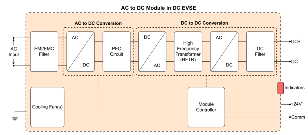
DC EVSEs consist of multiple lower-power AC-to-DC converter modules. Each module is a self-contained unit responsible for efficient and safe power conversion. The block diagram below illustrates a typical module configuration. Let’s delve into the module’s components, interfaces, and functionalities to understand the EVSE system better.

Interfaces
The module interfaces with various systems within the EVSE to facilitate seamless operation:
AC Input
- Single Phase or Three Phase: Accepts power from the electrical grid, depending on the EVSE’s design.
DC Output
- DC+ and DC-: Provides high-voltage DC power directly to the EV battery, ensuring efficient energy transfer.
Low-Voltage Interfaces
- 24V Supply: Powers control systems, sensors, auxiliary systems, and cooling fans.
- Communication Interface (e.g., Ethernet or CAN): Ensures real-time data exchange with the main EVSE controller for monitoring and operational control.
Indicators
- LEDs or Status Lights: Signal warnings, faults, or operational status using various colors.
Safety
- Ground Connection: Grounds the module’s metallic body to mitigate electrical hazards and ensure compliance with safety regulations.
Major Components and Their Functions
The module comprises several critical components that work together to achieve efficient and safe charging:
EMI/EMC Filter
- Filters out electromagnetic interference and ensures compliance with electromagnetic compatibility standards to prevent interference with other systems.
AC to DC Conversion
- Converts the incoming AC power from the grid into DC power, serving as the initial low-frequency conversion stage essential for subsequent processing.
PFC Circuit
- Power Factor Correction (PFC) is used to improve the efficiency of power conversion by ensuring that the input current is in phase with the input voltage. PFC helps to reduce the amount of wasted power and harmonics in the system. It corrects the power factor, typically aiming to achieve a value close to 1, meaning the power is used more effectively. This results in less strain on the electrical grid and ensures that the OBC operates with optimal performance.
DC to AC Conversion
- Converts DC power into high-frequency AC power. The reason for converting to high-frequency AC is that high-frequency AC allows for smaller, more efficient components like transformers, which are used in the next stage.
High-Frequency Transformer
- The high-frequency transformer is used to step up or step down the voltage while maintaining a high-frequency AC signal. The high-frequency nature of the transformer allows it to be much smaller and lighter than traditional low-frequency transformers, making it ideal for compact designs in an OBC. The transformer also provides electrical isolation between the input and output circuits, which is important for safety.
AC to DC Conversion (Secondary)
- Converts high-frequency AC back to DC after the transformer stage. This ensures the output power is suitable for the battery.
DC Filter
- Smoothens the output DC to ensure it is stable and free of ripples before being delivered to the battery. Clean DC power is critical for battery health and longevity.
Module Controller
- A microcontroller that manages all module operations, including power conversion, monitoring, communication, and safety protocols. It ensures that the module operates within predefined parameters and responds to system inputs dynamically.
Sensors
- Monitors various parameters, including:
- Input AC phase voltages, AC phase currents, and AC frequency.
- Output DC voltage and DC current.
- Temperature at critical points for thermal management.
Protection Mechanisms
- Provides overvoltage and overcurrent protection at both the input and output.
- Includes thermal protection to prevent overheating.
Cooling Fan(s)
- Regulate module temperature to prevent overheating and maintain operational efficiency.
Major Functions of the Module in EVSE:
The module performs several key functions to ensure reliable and efficient charging:
1. Charging Modes:
- Constant Current (CC) Mode: Maintains a steady current during the initial charging phase, which is crucial for rapidly increasing battery charge.
- Constant Voltage (CV) Mode: Maintains a steady voltage as the battery nears full charge to prevent overcharging.
- The module operates in CC and CV modes as directed by the main EVSE controller, ensuring optimal charging profiles based on EV requirements.
3. Fault Handling and Derating:
- Operates in a derating mode under fault conditions, such as high temperatures, to prevent module damage.
4. Wide Operating Range:
- Supports input AC phase voltages from 80V to 270V (approx..) and frequencies from 45Hz to 65Hz (approx..), ensuring compatibility with various grids.
- The output DC operating voltage range is to accommodate most EVs, typically up to 500V or 1000V.
5. Power Ratings:
- Module power ratings range from 10kW to 30kW, scalable based on the EVSE’s requirements.

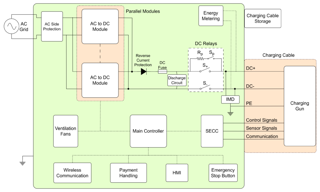
Modules are the building blocks of EVSE. Depending on the needed power level of EVSE, modules are connected in parallel. Below picture shows the block diagram of an EVSE with major components.
EVSE Components and Their Functionalities
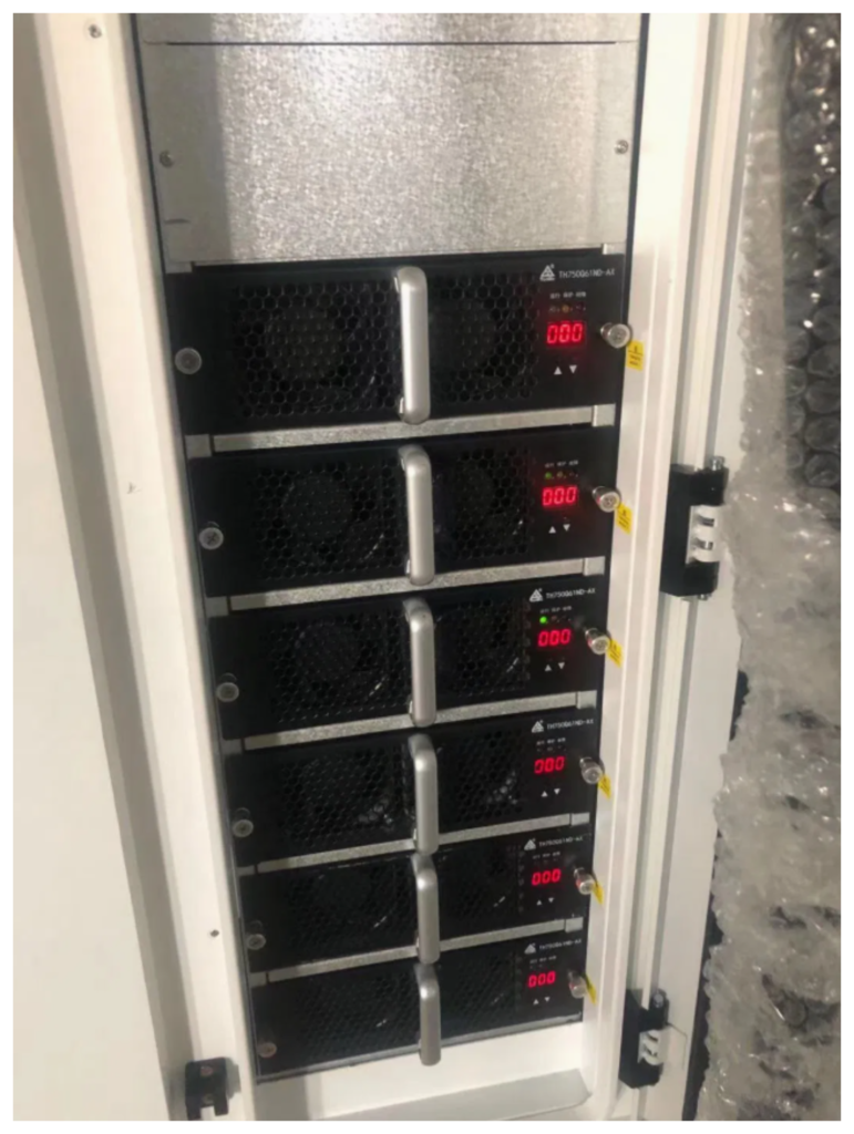
1. Parallel Modules
- Modules are connected in parallel to scale up the power delivery capacity of the EVSE. Each module operates independently but synchronously, responding to commands from the main controller.
- This arrangement ensures redundancy; if one module fails, others can continue operating, minimizing downtime.
- The modules handle AC-to-DC conversion, current regulation, and communication with the EVSE controller to maintain optimal charging performance as mentioned in the Module functional details in the above sections.
2. AC Side Protection
- Protects the EVSE from over voltages, over currents, and short circuits.
- Incorporates circuit breakers, surge protectors, and fuses to disconnect the power supply during fault conditions, safeguarding the modules and connected EVs.
- Ensures compliance with safety standards and prolongs the lifespan of the equipment.
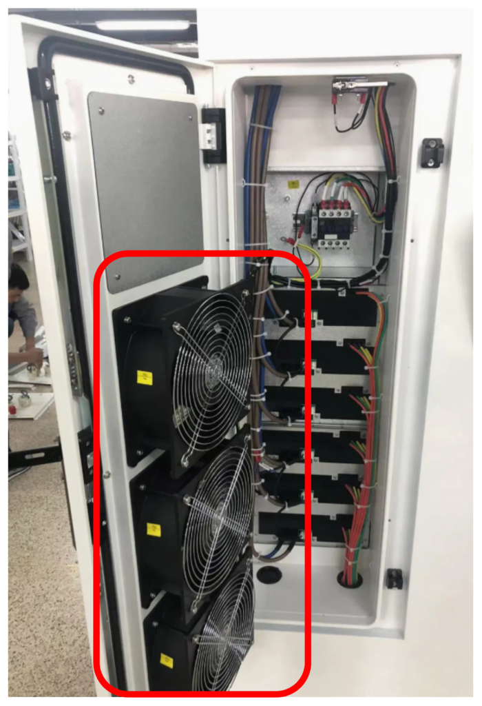
3. Ventilation Fans
- Provide active cooling to the modules and other components within the EVSE enclosure.
- Regulate temperature to prevent overheating, which could impair performance or cause failures.
4. Wireless Communication
- Facilitates communication with service providers for software updates, diagnostics, and real-time monitoring.
- Enables remote troubleshooting, performance analytics, and firmware upgrades to keep the EVSE operational and secure.
- Supports integration with smart grid systems for load management and energy optimization.
5. Main Controller
- Acts as the brain of the EVSE, coordinating all activities, including power conversion, communication, and safety protocols.
- Monitors the status of modules, interfaces, and sensors, ensuring seamless operation.
- Executes charging algorithms to deliver the correct voltage and current profiles as per the EV’s request.
- Provides fault detection, logs operational data, and interfaces with the user through the HMI.
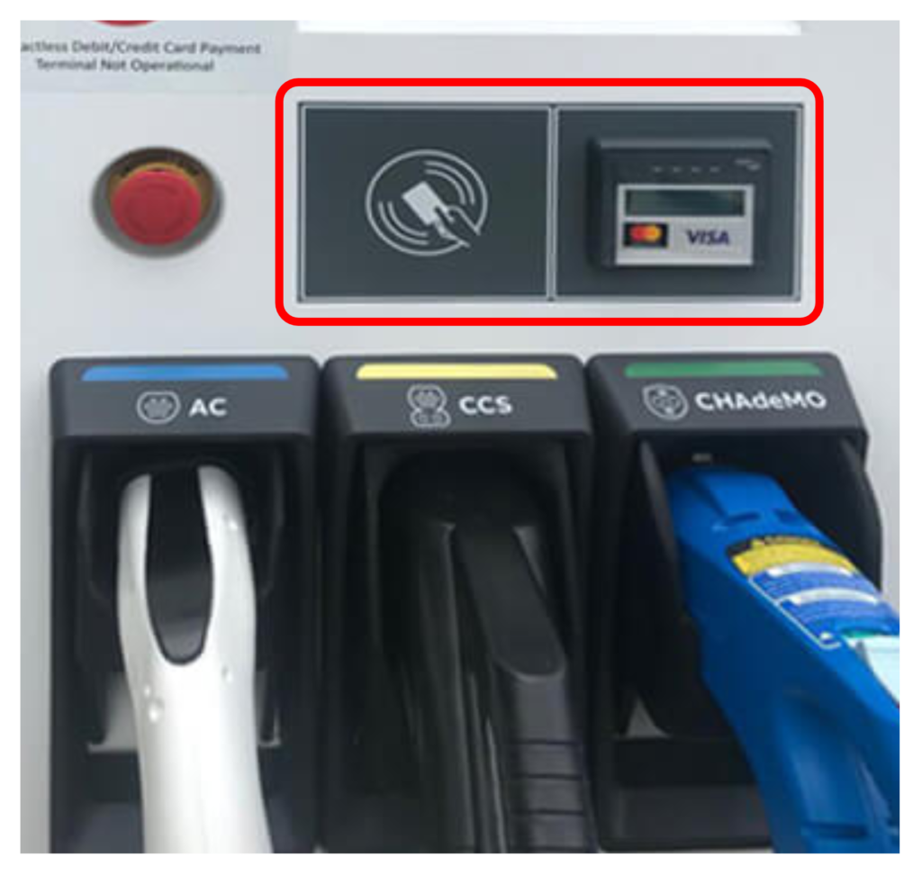
6. Payment Options
- Supports various payment methods such as RFID cards, mobile apps, contactless payments, and credit/debit cards.
- Ensures secure transactions through encryption and authentication protocols.
- Integrates with billing systems to provide real-time cost updates and usage receipts.
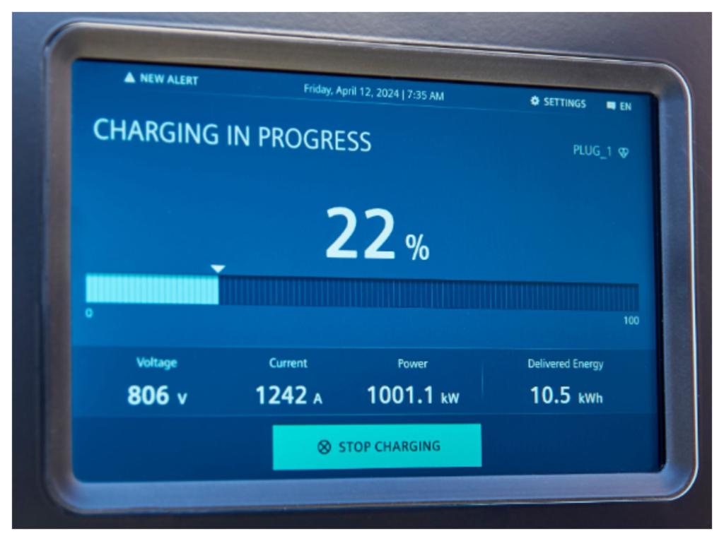
7. HMI (Human-Machine Interface)
- Provides a user-friendly interface for customers to initiate, stop, monitor, and control the charging process.
- Displays information such as charging status, time remaining, cost, and error messages.
- Allows users to select charging connector options (when multiple connectors are present), Language Preferences, and Help/Support Options.
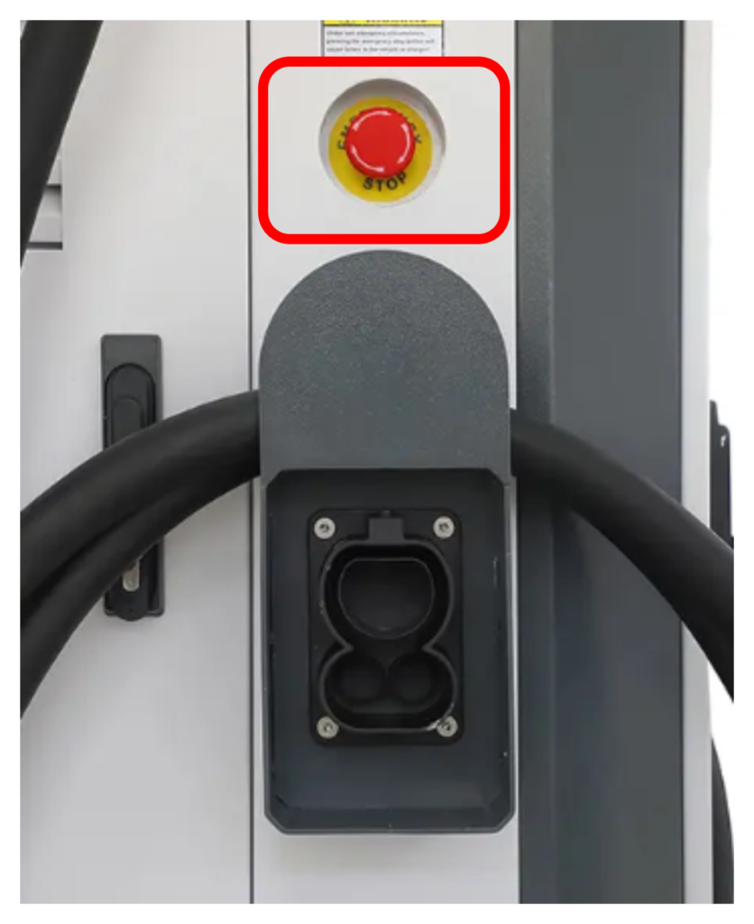
8. Emergency Stop Button
- The emergency stop button is a critical safety feature designed to immediately halt all charging operations in the EVSE during emergencies or hazardous situations.
- When pressed, it disconnects the power supply to the charging cable and isolates the EVSE modules, ensuring no current flows to or from the vehicle.
- This mechanism prevents potential risks such as electrical fires, equipment damage, or user injury.
- The system remains inactive until the fault or emergency is addressed, and the button is reset manually, ensuring controlled reactivation of the EVSE.
- Its prominent placement and clear labeling make it accessible and easy to use in urgent scenarios.
9. Reverse Current Protection
- Prevents backflow of current from the EV’s battery into the EVSE, protecting the modules and grid.
10. DC Fuse
- Protects the DC output circuit from overcurrent conditions.
- Blows in the event of excessive current, isolating the faulty section and preventing damage to the EV or EVSE.
11. Discharge Circuit
- Discharges residual capacitance on DC lines and charging cables after a charging session.
- Prevents accidental electric shocks and ensures safety during cable disconnection.
- Operates automatically upon completion of charging or during emergency stop conditions.
12. DC Relays
- Enable or disable the DC power supply to the charging cable based on commands from the main controller.
- Support precharge circuits for CCS1, CCS2, and NACS charging, allowing the system to stabilize voltage before establishing a full connection.
- For GBT and CHAdeMO standards, precharging is managed by the EV, eliminating the need for precharge circuits in the EVSE.
13. Isolation Monitoring Device (IMD)
- Continuously monitors insulation resistance between the DC lines (DC+, DC-) and ground.
- Detects faults such as insulation degradation or short circuits, triggering protective actions like stop charging or warning on HMI to prevent hazards.
14. Energy Metering
- Measures energy consumption accurately during charging sessions.
- Provides accurate billing information and supports load balancing by tracking power usage.
- Logs data for analytics and regulatory compliance.
15. Charging Cable Storage
- Ensures safe and convenient storage of charging cables when not in use.
- Prevents cable damage and tripping hazards by keeping cables organized.
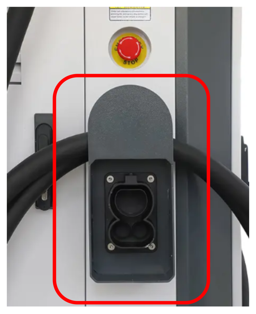
16. Charging Cable
- Delivers power from the EVSE to the EV, ensuring a safe and efficient charging process.
- Multiple standards are used worldwide, each tailored to regional or vehicle-specific requirements:
- CCS1: Common in North America.
- CCS2: Predominantly used in Europe.
- GBT: Widely adopted in China.
- CHAdeMO: Primarily used in Japan.
- NACS (Tesla): Mainly used in North America.
- Typically cables with power ratings below 150 kW does not require liquid cooling. For higher power levels exceeding 150 kW, liquid-cooled cables are essential to manage heat and maintain performance. Without cooling, the cable dimensions would become excessively large to handle the required current.
- High-quality materials and insulation are used to ensure durability, flexibility, and compliance with safety standards.
17. SECC (Supply Equipment Communication Controller)
- Serves as the primary communication hub between the EVSE and the EV, ensuring seamless data exchange for efficient and safe charging.
- Continuously monitors critical signals from the charging connector, including:
- Terminal Temperatures: Tracks real-time temperature at the charging terminals to prevent overheating and ensure safe operation.
- Cable Connection Status: Detects whether the charging cable is properly connected to the EV, ensuring a secure interface before initiating charging.
- Locking Mechanism Status: Manages and monitors the locking motor operations to ensure the connector is securely latched to the vehicle during charging.
- Control of Locking Motors: Actuates and releases locking mechanisms based on charging progress and user input, providing safety and convenience.

In conclusion, as the adoption of electric vehicles (EVs) continues to rise, the demand for efficient, reliable, and rapid charging solutions has never been more critical. DC EVSE plays a pivotal role in meeting these demands, offering faster charging times and ensuring the seamless integration of EVs into daily life. With advancements in technology and the growing infrastructure of charging stations, DC fast charging is set to become an integral part of the global shift toward sustainable transportation.
EV Charging Explained – Everything you need to know about Electric Vehicle Charging