Isolation Monitoring in EVs: Comprehensive Insights
Isolation monitoring is a crucial safety measure within high-voltage (HV) vehicle systems. Let’s explore the details in the following article for a comprehensive understanding of this critical aspect.
What is Isolation Resistance or Insulation Resistance?
Isolation resistance, also known as insulation resistance, is a measure of the electrical resistance between two conductive parts in a system, typically separated by an insulating material. In the context of electric vehicles (EVs), it signifies the resistance between the HV lines and the vehicle chassis (DC+ to chassis and DC- to chassis).
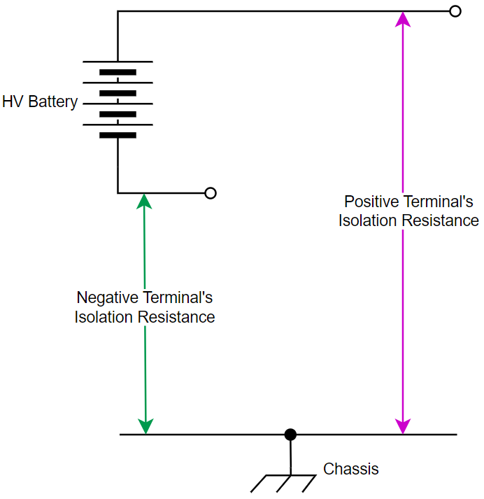
What does it Mean by Isolation Monitoring?
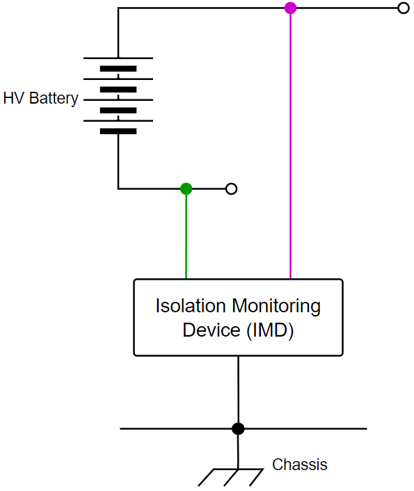
Isolation monitoring is a systematic approach to continuously assess the isolation resistance in an EV’s HV system. It involves monitoring (or measuring) the electrical resistance between the HV lines and the vehicle chassis (DC+ to chassis and DC- to chassis) to ensure that it remains within the safe limits. The circuit or device which is used for isolation monitoring is commonly referred Isolation Monitoring Device (IMD).
Why is Isolation Monitoring Necessary?
Isolation monitoring plays a crucial role in preventing electric shock hazards to personnel and mitigating the risk of fire in EVs.
In the automotive sector, HV is defined as voltage greater than 30 V AC or 60 V DC. With most modern EVs designed to operate at 400 V DC or higher, the potential danger associated with HV contact becomes significantly prominent. The consequences of such contact can be life-threatening.
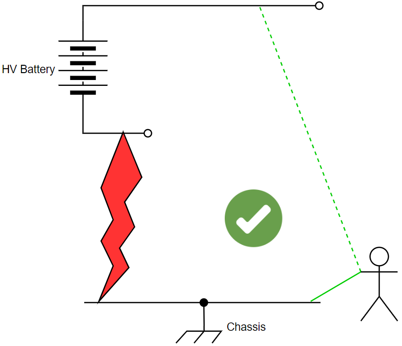
Isolation monitoring is indispensable to address these risks. In the event of an isolation failure between the HV negative line and the chassis, the fault itself might not pose immediate danger. However, if a person, particularly a service technician, comes into contact with the vehicle chassis and the positive line, it creates an electrical shock hazard with the potential for life-threatening or severe physical injuries. (This scenario is valid for isolation failure between positive line and chassis)
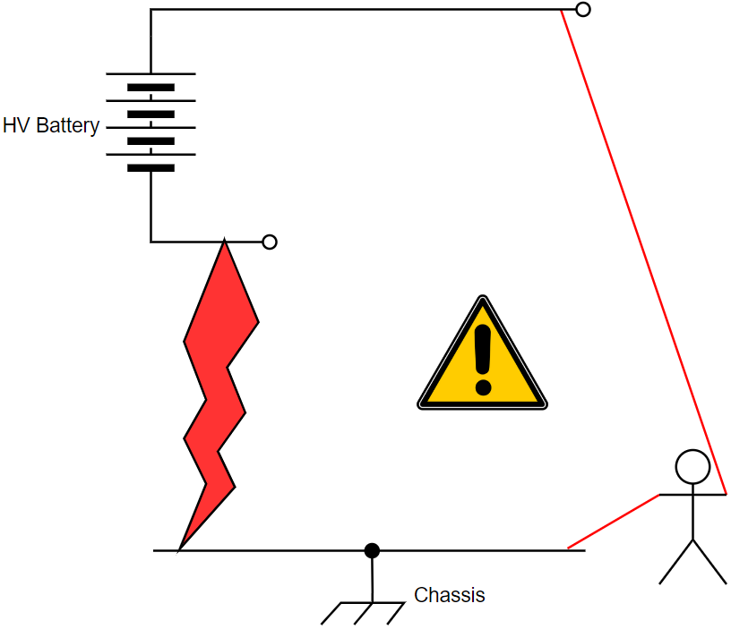
Furthermore, isolation failures at both “positive to chassis” and “negative to chassis” can lead to a short circuit in the HV system, leading to a fire hazard.
Isolation monitoring serves as a proactive measure, promptly detecting failures and alerting personnel through messages on the vehicle’s display or diagnostic tools. In the event of an isolation failure, the battery can take immediate protective actions, such as disconnecting its contactors or inhibiting them from closing, effectively preventing the supply of voltage to the HV bus.
What is the Safe Isolation Resistance Level in EVs?
To adhere to safety regulations in EVs, the isolation resistance between the HV lines and the chassis must meet specific criteria. According to regulations, for DC system, the minimum isolation resistance should be 100 Ω/volt of the working voltage, and for AC system, it should be 500 Ω/volt of the working voltage.
For instance, in a 400 V battery system EV, the minimum isolation resistance required for safe operation is calculated as 400 V × 100 Ω/V = 40k Ω. Any value below this threshold is considered an isolation fault. Similarly, in the case of a 230 V AC system, which is used to power sockets in the vehicle, the required isolation resistance for safe operation is 230 V × 500 Ω/V = 115k Ω.
From above, it can be observed that AC requires a higher isolation resistance than DC, and the rationale behind this includes the following factors:
- Lethality at Similar Voltages: When comparing 230V AC and 230V DC, AC may present a higher level of danger than DC at the same voltage. Typically, AC is rated in terms of RMS values, which are lower than peak values. Therefore, a 230V AC supply translates to a peak voltage of 325V (230 * √2 = 325). In practical terms, this means that if you have a 230V AC supply, it oscillates between a maximum of 325V and a minimum of -325V, alternating 60 times per second (60 Hz frequency). In contrast, if it were DC, the voltage would remain constant at 230 V.
- Heart Fibrillation Risk: Heart Fibrillation is considered as one of the main reasons of death resulting from electric shock, and the human body is more susceptible to fibrillation when exposed to AC compared to DC. Both AC and DC currents have the potential to induce heart fibrillation typically at 50 mA of AC (rms, 60 Hz) or 300 – 500 mA of DC or higher.
- Body Impedance and Frequency Dependency: The impedance of the human body is influenced by the frequency of the electrical voltage. It is higher at lower frequencies and gradually decreases as the frequency increases. DC, having a frequency of 0 Hz, exhibits the highest impedance. In contrast, typical AC operates at frequencies around 50 Hz or 60 Hz, resulting to a lower impedance. Due to the lower impedance for AC, allowing for higher current flow, the potential severity of an electric shock in AC tends to be relatively higher compared to DC.
- “Let-Go” Current Threshold: The “Let-Go” Current Threshold is the maximum electric current flowing through the human body at which an individual can release themselves from electrical contact. In comparison, the let-go threshold for DC current is higher than that for AC current. This implies that even at lower AC currents, a person may find it challenging to release themselves from electrical contact, potentially leading to electrocution. Typically, the let-go current for AC ranges from 3 to 22 mA, while for DC, it ranges from 15 to 88 mA.
What are the Reasons for Isolation Failures or Degradation?
Isolation failures or degradation can result from various factors, and a few of these reasons are listed below:
- The influence of impulse currents (sudden currents to drive the motors during vehicle operation) on the dielectric strength of cable insulation.
- Exposure to harsh environmental conditions such as extreme temperatures, high humidity, or corrosive chemicals.
- Vibrations or mechanical stresses stemming from vehicle operation or accidents.
- Aging and wear of insulation materials over time.
- Accumulation of dirt leading to the creation of conductive pathways.
- Incidents like coolant leakage compromising isolation.
- Tools left in the battery pack during service.
Categories of Isolation Faults:
Isolation faults are broadly categorized into two types:
- Symmetric Faults: This fault type involves a scenario where the isolation between all power lines and the chassis drops below the safe limit, and all power lines will have uniform (approximately) isolation resistance.
- Asymmetric Faults: In an asymmetric fault scenario, the isolation between at least one power line and the chassis falls below the safe limit, and different power lines exhibit different isolation resistances.
It’s worth noting that detecting symmetric faults is generally more challenging compared to the asymmetric faults.
Power lines in DC systems: Positive terminal and Negative terminal.
Power lines in AC systems: Phase(s) and Neutral.
Different Isolation Monitoring Techniques:
There are various techniques for isolation monitoring, with two prominent methods being the electric bridge switch and AC current injection.
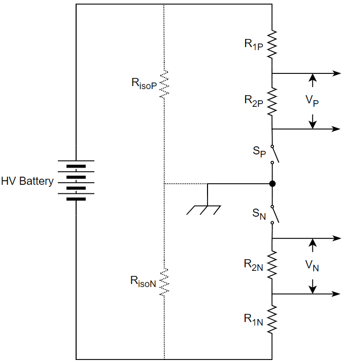
- Electric Bridge Switch Method: In this method, a known resistive branch is strategically switched across the isolation barrier. The isolation resistance is estimated by analyzing the voltages VP and VN during different states of the switches.
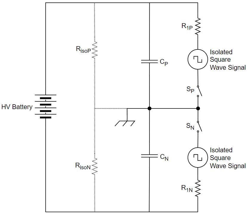
- AC Current Injection Method: The AC current injection method involves generating an isolated square wave signal. This signal is then injected into the RC circuit positioned between the high-voltage lines and chassis. By analyzing the charge and discharge times of the capacitor in the circuit, the isolation resistance is estimated.
In summary, ensuring meticulous isolation monitoring in electric vehicles is essential to avoid life-threatening dangers posed by high voltage. With the advancing technology and increasing prevalence of electric cars, prioritizing safety measures is crucial. Understanding isolation resistance, monitoring methods, and fault categories contributes to a safer and more reliable electric vehicle experience. By emphasizing these measures, the electric vehicle industry can flourish while maintaining a secure environment for both users and technicians.
EV Charging Explained – Everything you need to know about Electric Vehicle Charging