Understanding the High Voltage Junction Box (HVJB) in EVs
As electric vehicles (EVs) continue to evolve, efficient and safe management of high-voltage (HV) power distribution is crucial. At the heart of this distribution system is the High Voltage Junction Box (HVJB)—a customizable power distribution and protection hub that connects critical high-voltage subsystems within the EV. Often overlooked compared to traction motors or battery packs or OBC, the HVJB plays a central role in connecting and protecting the high-voltage subsystems of an EV.
However, it’s important to note that the architecture of an HVJB is not fixed. Its layout, contents, and functionalities are highly dependent on the product and design choices of the vehicle manufacturer. This article explores the typical design of an HVJB, its main functions, and the key components it may contain in modern EVs.
1. What is a High Voltage Junction Box (HVJB)?
The High Voltage Junction Box (HVJB) is a centralized enclosure within an EV where high-voltage cables and circuits from different subsystems are connected, protected, and distributed. It acts as a control and distribution hub for high-voltage electricity, ensuring power is safely and efficiently delivered to key systems such as:
- High-voltage battery
- Traction inverter
- On-board charger (OBC)
- DC charging cables
- DC-DC converter
- High-voltage auxiliary loads (e.g., electric air conditioning compressor)

2. Purpose and Functions of HVJB
The HVJB serves as the central interface for routing high-voltage power among various subsystems. It provides:
a. Power Distribution
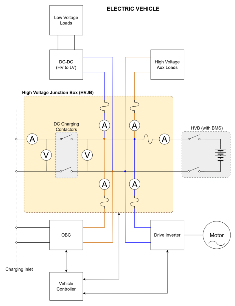
The primary function of the High Voltage Junction Box (HVJB) is to manage electrical connections and distribute high-voltage power between key components of the vehicle. For example, during driving, it channels power from the high-voltage battery to subsystems like the traction inverter and DC-DC converter. During charging, it routes power from the on-board charger (OBC) or DC charging port to the battery and other relevant components. The HVJB ensures that each system receives the appropriate voltage and current levels required for safe and efficient operation.
b. Electrical Protection
The HVJB plays a crucial role in safeguarding the vehicle’s high-voltage electrical architecture. Each high-voltage output branch typically includes overcurrent protection devices such as fuses or circuit breakers. These components are designed to disconnect faulty circuits rapidly in the event of an overload or short circuit, preventing damage to equipment and reducing the risk of fire or thermal events. Additionally, the HVJB may include voltage monitoring and fault detection circuits to identify abnormal conditions like overvoltage, undervoltage, ground faults, or insulation failures, thereby enabling timely protective actions.
c. Real-time Monitoring
Embedded within the HVJB is a control and sensing PCB that continuously monitors various parameters critical to the vehicle’s operation and safety. This includes:
- Voltage levels across different branches
- Current flowing to each subsystem
- Internal temperatures of the junction box
- Status of contactors and fuses
Sensors such as Hall-effect sensors, shunt resistors, and NTC thermistors collect data, which is then processed and transmitted to the vehicle control units. Real-time monitoring enables dynamic diagnostics, early fault detection, and predictive maintenance, contributing to vehicle reliability and safety.
d. Safe Isolation and Switching
To prevent electrical hazards during maintenance, charging, or shutdown events, the HVJB ensures safe electrical isolation between high-voltage circuits and the vehicle chassis or low-voltage systems. High-voltage contactors are used to disconnect power lines under both normal and fault conditions. In many designs, precharge circuits are included to manage the initial inrush current when energizing capacitive loads like the inverter, ensuring a smooth and safe startup. These switching operations are tightly controlled and monitored to avoid arcing or contactor welding, especially in high-current conditions.
e. Communication with Vehicle Controllers
.The HVJB is not a passive component—it actively communicates with the vehicle’s electronic control units via CAN (Controller Area Network) or other automotive communication protocols. The control PCB inside the HVJB sends real-time data such as:
- Voltage and current values
- Temperature readings
- Contactor status
- Fault codes or warnings
This two-way communication allows the Vehicle Control Unit (VCU) or Battery Management System (BMS) to make informed decisions, such as energizing or de-energizing specific loads, initiating shutdowns during faults, or adjusting power delivery based on thermal conditions. Effective communication ensures system-wide coordination and operational safety.
3. Typical Components of HVJB
A HVJB is a compact and robust unit that integrates multiple electrical and electronic components to manage high-voltage power safely and intelligently. Below is a detailed breakdown of the typical components found inside an HVJB:
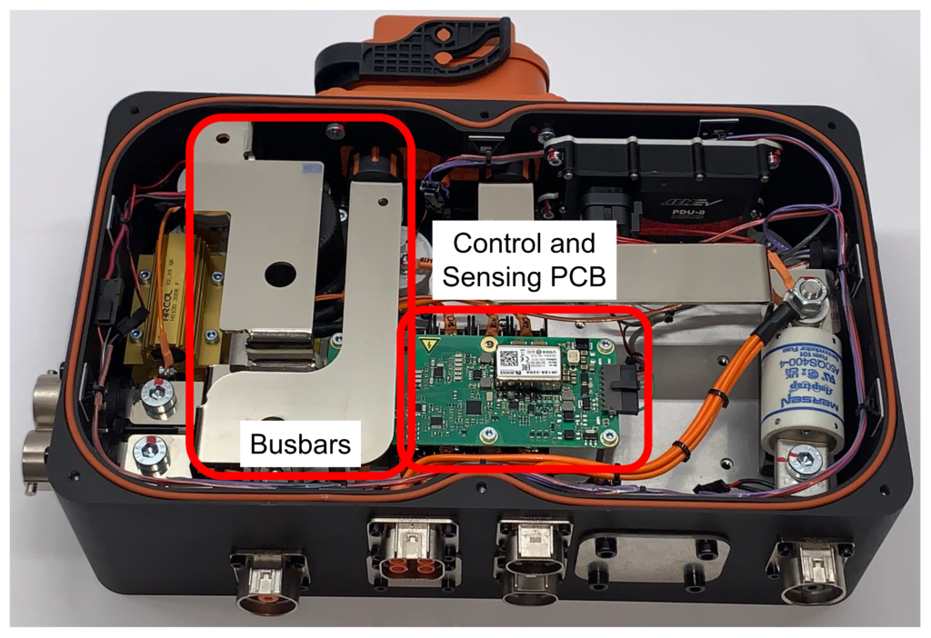
a. Busbars
At the heart of the HVJB are busbars—thick conductive bars usually made of copper or aluminum. These busbars serve as the primary channels for distributing high-voltage power among key vehicle systems, such as the traction inverter, DC-DC converter, on-board charger (OBC), and auxiliary loads like the electric air conditioning compressor. Busbars are engineered for minimal resistance and optimal thermal performance, allowing them to carry hundreds of amperes without significant heat buildup. Their layout is carefully designed to ensure efficient power flow and to reduce electromagnetic interference.
b. Fuses
Each high-voltage output from the HVJB is typically protected by a dedicated fuse. These fuses are critical for system safety—they are designed to interrupt the circuit quickly in the event of an overcurrent situation, such as a short circuit or sudden load spike. By sacrificing themselves when needed, fuses prevent further damage to expensive components downstream and mitigate the risk of electrical fires or thermal runaway. The selection of fuses is based on expected current loads, voltage ratings, and time-current characteristics tailored for automotive use.
c. High-Voltage Contactors and Relays
To enable or disable power to individual circuits within the vehicle, high-voltage contactors or relays are employed. These electrically controlled switches are capable of handling large current and voltage levels, and they play a vital role in the safe operation of the EV. For instance, DC charging contactors are often located within the HVJB to control the connection between the DC charging port and the high-voltage battery. Depending on the design, the junction box may also house the battery-side contactors (positive, negative, and precharge), although these are sometimes integrated within the battery pack itself. In systems where precharge is managed in the HVJB, a precharge resistor is included to limit inrush current when energizing capacitive loads like inverters.

d. Voltage and Current Sensors
Precise control and safety in EVs depend heavily on voltage and current sensors inside the HVJB. These sensors continuously monitor the electrical parameters across various high-voltage paths. For current measurement, technologies such as Hall-effect sensors or shunt resistors are used, offering real-time data with high accuracy. Voltage is typically measured using isolated voltage divider networks or specialized sensing ICs. These sensors not only help regulate power distribution but also enable the vehicle to detect faults like overcurrent, undervoltage, or ground leakage early.
e. Temperature Sensors
Thermal safety is critical in high-voltage systems, and the HVJB includes strategically placed temperature sensors—usually NTC thermistors—to monitor the temperature of key components like contactors, fuses, and busbars. These sensors feed temperature data to the control system, which can then trigger derating, activate cooling systems, or shut down power to prevent overheating. Effective thermal management extends the life of components and ensures safe operation under varying load and environmental conditions.
f. Isolation Monitoring Circuit (Optional)
The isolation monitoring circuit is an optional component in the HVJB, depending on the overall vehicle electrical architecture. Its primary function is to monitor the insulation resistance between the high-voltage system and the vehicle chassis (ground). This is crucial for detecting potential leakage paths or faults that could lead to safety hazards.
g. Control and Sensing Circuit PCB
The control and sensing circuit board acts as the intelligence core of the HVJB. This printed circuit board (PCB) collects data from all voltage, current, and temperature sensors, processes it in real time, and transmits critical information to the vehicle’s control systems—such as the Vehicle Control Unit (VCU) or Battery Management System (BMS)—via automotive communication protocols like CAN bus. The PCB also controls the actuation of contactors, ensuring that power delivery and shutdowns happen in a coordinated and safe manner. In essence, this control board transforms the HVJB from a passive box into a smart power gateway for the electric vehicle.
h. Insulators and Environmental Seals
High-voltage circuits require strict electrical isolation to ensure user safety and component longevity. The HVJB uses various insulating materials and mechanical barriers to prevent arcing or short circuits between conductive parts. Additionally, to withstand harsh automotive environments, the entire junction box is sealed with gaskets and potting materials, enabling it to meet ingress protection standards such as IP67 or IP6K9K. These seals protect internal electronics from dust, water, and chemical exposure, ensuring reliable operation across diverse climatic conditions.
i. Shielded Cable Entries and HV Connectors
High-voltage cables in the HVJB are typically routed through shielded cable entries or HV connectors, depending on the design.
- Shielded cable entries ensure proper environmental sealing (IP67/IP6K9K) and electromagnetic interference (EMI) protection, maintaining the integrity of the high-voltage system.
- HV connectors provide a more modular connection, often incorporating HVIL (High Voltage Interlock Loop) for added safety. These connectors facilitate easy assembly and maintenance, ensuring safe and reliable connections between the HVJB and external high-voltage components.
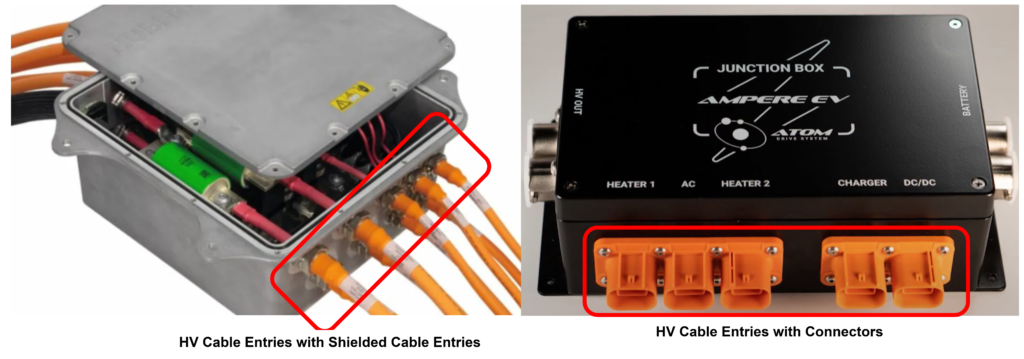
Both methods play a crucial role in ensuring safe, robust high-voltage connections while maintaining system performance and reliability.
j. Low Voltage Connector
Provides low voltage power to the sensing and control circuits within the HVJB, and also includes communication lines.
k. Enclosure
The enclosure of the High Voltage Junction Box (HVJB) serves as a critical protective component, housing and safeguarding all internal electrical and electronic elements. Designed to withstand harsh automotive environments, the enclosure ensures physical protection from external factors such as dust, moisture, vibration, and thermal stress. Typically made from high-strength material like aluminum, it also provides excellent insulation and EMI (Electromagnetic Interference) shielding.
4. Physical and Environmental Design Considerations
Designing a High Voltage Junction Box (HVJB) for electric vehicles involves several physical and environmental considerations to ensure safety, reliability, and long-term durability under demanding conditions.
a. Thermal Management
While HVJBs generally do not produce significant heat during normal operation, thermal management is still a key consideration—especially in high-power applications or compact designs with limited airflow. Passive cooling techniques such as integrated heat sinks, thermal pads, or conductive housing materials may be employed to dissipate residual heat and maintain component longevity.
b. Environmental Sealing
To ensure reliable operation in harsh automotive environments, HVJBs are engineered with robust sealing mechanisms to protect against dust, water, and chemical exposure. Enclosures typically meet ingress protection standards like IP67 (dust-tight and waterproof up to 1 meter depth) or IP6K9K (resistant to high-pressure, high-temperature water jets), depending on the vehicle’s requirements. Additionally, EMI shielding—through metalized coatings, conductive gaskets, or internal shielding layers—may be incorporated to prevent electromagnetic interference from affecting sensitive circuits within or around the junction box.
c. Mechanical and Electrical Isolation
High-voltage circuits inside the HVJB are mechanically and electrically isolated to ensure safety and prevent dielectric breakdown. Adequate creepage and clearance distances are maintained in accordance with international safety standards, such as IEC 60664, to withstand expected overvoltages and prevent arcing, especially in high-humidity or contaminated environments. This isolation is critical not only for occupant safety but also for the protection of low-voltage control systems interfacing with the HVJB.
The HVJB is a critical component that ensures the reliable and safe operation of electric vehicles. As the automotive industry advances toward more powerful, efficient, and compact EV architectures, the HVJB must evolve with integrated intelligence, higher voltage compatibility, and enhanced safety features. Understanding its role provides deeper insight into the inner workings of electric powertrains and the future of electric mobility.
EV Charging Explained – Everything you need to know about Electric Vehicle Charging