Precharge and Stuck Contactors in HV System: Comprehensive Overview
In an electric vehicle (EV), the high-voltage (HV) system comprises essential components like the HV battery, contactors, and vehicle loads such as electric motor system and the HV to low voltage (LV) power converter etc.
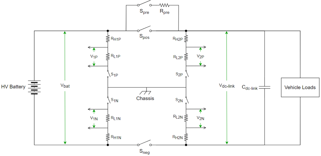
Here,
Spre = Precharge contactor
Spos = Positive contactor
Sneg = Negative contactor
Rpre = Precharge resistor
Cdc-link = DC link capacitance = The DC link capacitance refers to the cumulative capacitance of all connected input capacitances of power electronics components such as motor control inverters, HV to LV converters.
S1P, S2P, S1N, S2N = Switches to enable/disable the resistive divider circuits which are used for voltage measurement.
RH1P, RH2P, RH1N, RH2N = High side resistors of the resistive divider circuits. Typical resistance values for these resistors is in Mega Ohms (MΩ)
RL1P, RL2P, RL1N, RL2N = Low side resistors of the resistive divider circuits. Typical resistance values for these resistors is in Kilo Ohms (kΩ)
What is Precharge?
Precharge is a process of charging the DC link capacitance in a controlled manner with a limited current before activating the HV to DC bus (or DC link). Precharge is the initial phase within the HV activation process in the HV DC system.
Why is Precharge Essential?
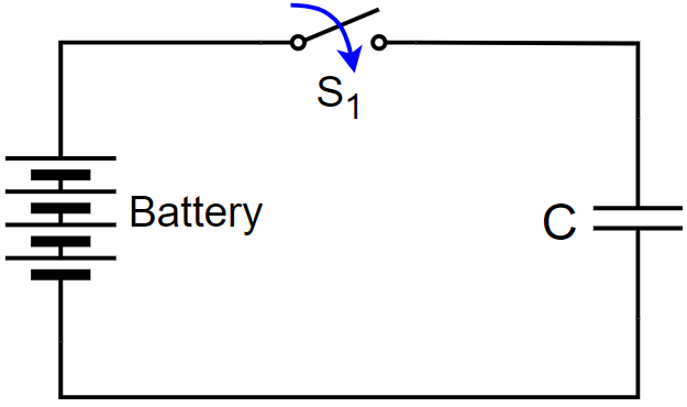
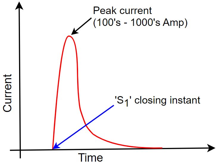
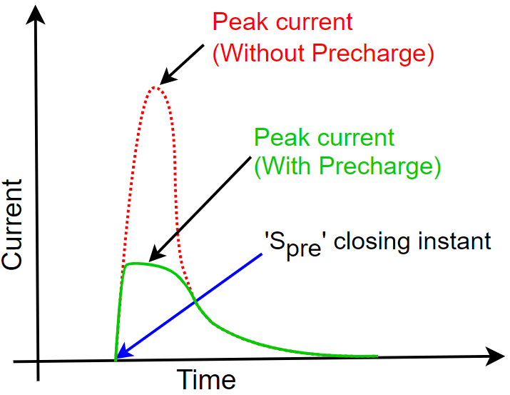
When voltage is applied to an uncharged capacitor, it initiates the charging process. Initially, an inrush of current occurs, gradually reducing to zero as the capacitor reaches full charge. The magnitude of the inrush current can range from hundreds to thousands of amperes, depending on the voltage levels. The internal resistance of both the battery and the capacitor is exceptionally low, potentially within the milliohm range or even less, leading to an absence of built-in limitations on the inrush current.
Uncontrolled inrush currents can lead to the following failures:
- Capacitor Damage: Unrestricted inrush currents can cause damage to the capacitor, potentially reducing its lifespan.
- HV Battery Life Reduction: The overall life expectancy of the HV battery may be compromised.
- HV Battery Fuse Blowout: Excessive inrush currents have the potential to blow the fuse of the HV battery.
- Welded Contactors: The generation of high heat at the contacts during uncontrolled inrush currents can result in welded contactors, causing them to become stuck in the closed position — Inrush current is the most common reason of contactor welding.
- Impact on HV Cable Isolation Resistance: Inrush currents can adversely affect the dielectric strength of HV cables, potentially compromising the isolation resistance of the cables.
To proactively mitigate these potential failures, it is crucial to control and limit inrush currents, and this is precisely the purpose of the precharge process. By systematically regulating the capacitor charging process, precharge ensures that inrush currents are kept within manageable limits, thus safeguarding the integrity and longevity of the components within the HV system.
How is Precharging Performed?
As discussed in the preceding sections, Precharging is the initial stage in the HV activation process. Let’s look into the comprehensive HV activation process, including the precharge phase.
The HV activation process consists of four systematic steps:
Step-1: Measure the voltage of the HV battery (Vbat)*. The measured voltage from this step is used in the subsequent precharge phase.
* The process/technique of measuring the voltage is described at the end of the article.
Step-2: Precharge: Close the Sneg and Spre contactors to initiate precharge through Rpre. Wait for the Vdc-link to rise almost equal to Vbat. Once Vbat and Vdc-link reach near equivalence (around 99%), precharge is considered as complete.
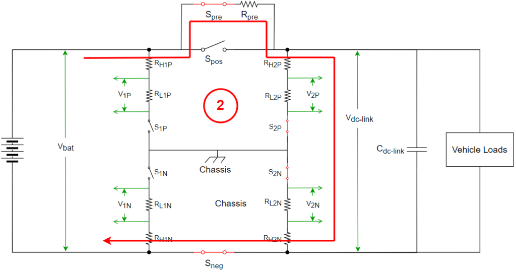
The value of Rpre depends on the system’s requirements for the precharge time (As the part of overall HV activation time). The selection process for Rpre is explained below:
When a resistor is connected in series with a capacitor, it forms a simple RC circuit. The time constant (T) of this circuit is calculated as R⋅C. The time constant represents the duration for the capacitor voltage to reach 63.2% of the supply voltage. It approximately takes 5T for the capacitor voltage to reach 99.33% of the supply voltage. For example, if a 400 Volt battery is connected to a DC bus with 6 mF of DC link capacitance, and the system needs to precharge in 1.5 seconds, the required resistor value can be calculated as follows:
5T = 1.5 seconds (desired precharge time)
1T = 1.5 / 5 = 0.3 seconds
T = R * C
0.3 seconds = R * 0.006 Farads
R = 0.3 / 0.006 = 50Ω
The peak current with the precharge resistor can be calculated as battery voltage (V)/R = 400/50 = 8A. It is evident that the peak current with the precharge resistor is significantly smaller compared to without the precharge resistor which is in the range from hundreds to thousands of amperes.
An important consideration is that loads on the DC bus should not be activated during precharge. If activated, precharge cannot be completed within the desired time, as the DC link capacitor cannot be charged in the specified timeframe. If precharge is not successfully completed within the designated time, it is considered as precharge failure, resulting in the termination of the HV activation process.
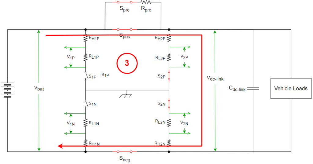
Step-3: Once precharge is completed, close the Spos, enabling the direct connection of the DC bus to the HV battery. As the capacitor is nearly charged to the battery voltage, there will be negligible or no inrush currents.
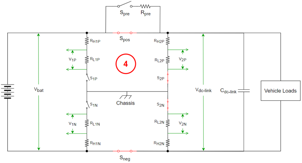
Step-4: Following the closure of Spos, proceed to open the Spre contactor. Opening of Spre is considered as successful HV activation. Now loads on the DC bus are allowed to draw the power from HV battery.
What are the Reasons for Precharge Failure?
Precharge failure in a high-voltage system can result from several factors, which include:
- Damaged Precharge Resistor: If the precharge resistor is damaged or its value has deviated from the intended value, it can lead to either excessively rapid or slow precharging. This deviation causes a failure to attain the required voltage levels within the specified time.
- Contactor Issues: Faults in the Spre or Sneg contactors, particularly when stuck open, can prevent the successful achievement of precharge.
- DC Link Capacitor Issues: Issues with the DC link capacitor, such as a short circuit or internal faults, can hinder the capacitor’s ability to reach the desired voltage. This situation results in precharge failure as the capacitor may not charge adequately.
- Activation of Loads During Precharge: Premature activation of loads on the DC bus throughout the precharge process can disrupt the charging sequence. This interference leads to a failure in reaching the necessary voltage levels within the prescribed time.
- Isolation Failure on the HV System: If there is an isolation failure in the system, it prevents the DC link capacitor from reaching the adequate voltage, contributing to precharge failure.
What is Stuck Contactors?
In the context of contactors, the term “stuck” denotes an unintentional scenario where the contacts, designed for the purpose of opening and closing, become immobile, fixed in a singular position. There are two primary types of stuck contactors:
- Stuck Closed
- Stuck Open
Now, let’s delve into more detailed insights about these scenarios.
1. Stuck Closed:
Stuck closed denotes a scenario where the contacts of a contactor remain closed despite being instructed to open. This situation typically arises from two primary causes. First, welding of the contacts within the contactor can lead to a firm bonding, preventing the intended opening. This scenario is also referred as “Welded Closed” contactors. Second, mechanical failures within the contactor, contributing to the inability of the contacts to open as intended.
The common causes for welded closed contactors include:
- Passing Higher Current than Contactor Rating: When the current flowing through the contacts exceeds their specified capacity, the contacts can overheat due to the contacts’ resistance. Over time, this heat buildup may lead to welding of the contacts.
- High Currents during Opening: Exposure to excessive electrical currents during the opening operation generates significant heat, potentially resulting in the welding of contacts. While not an immediate occurrence, repeated operations heighten the risk of welding over time.
- Overvoltage Conditions: Sudden surges in voltage, exceeding the contactor’s designed specifications, can induce arcing and contribute to the welding of contacts.
- Aging or Wear: Over the course of time, the contacts of a contactor undergo wear, leading to the development of uneven surfaces and increased contact resistance. This increased resistance elevates the risk of welding due to the higher heat generated.
- Frequent Cycling: Excessive and rapid opening and closing of contacts, referred to as frequent cycling, accelerate the aging process of the contactor. This increased aging amplifies the likelihood of welding, as explained in the preceding section.
- Mechanical Failures: Mechanical shocks or vibrations can result in damage to the relay’s springs within the contactors or cause breakage of the metallic contacts. These mechanical failures contribute to the contactors getting stuck in the closed position.
- Contaminant Accumulation: Aging contactors are more susceptible to the accumulation of dirt, dust, or other contaminants on their contact surfaces. These contaminants impede the smooth separation of contacts, fostering arcing and welding.
Consequences of Stuck Closed Contactors:
Encountering stuck closed contactors gives rise to significant concerns. Within a DC system, the presence of a single stuck contactor (either positive or negative), may not raise substantial concern, as it cannot establish a closed path for current. However, the situation becomes considerably more alarming when both contactors are stuck, presenting severe threats, as outlined below:
- Safety Implications: The stuck closed contactors raises serious safety concerns by exposing personnel to high voltages, posing an imminent risk of electric shock.
- Potential Equipment Damage: The failure to open contactors as intended during equipment’s malfunctions can result in substantial damage, impacting the reliability and functionality of the equipment.
- Risk of Fire: In the event of short circuits within the system, the failure to open contactors due to being stuck closed can escalate the risk of fire hazards.
2. Stuck Open:
Stuck open refers to a situation where the contacts of a contactor remain opened despite being instructed to close.
The common causes for stuck open contactors include:
- Mechanical Failures: Mechanical failures cover various issues, such as worn-out components or damage to the mechanical parts responsible for opening and closing contacts. These failures can lead to the contactors remaining in the open position, causing a stuck open condition.
- Relay Coil Failure: A failure in the relay coil may result in the inability to generate sufficient magnetic force. Two potential failures in the relay coil include an open circuit, resulting in no magnetic force, and a partial short circuit, leading to insufficient magnetic force to engage the contact. These situations can cause the contacts to remain stuck in the open position.
- Misalignment of Contacts: Misalignment refers to the improper positioning of contactor components, particularly the movable contacts. Misalignment can prevent the contacts from properly engaging, resulting in a stuck open condition where the contacts fail to close as intended.
- Presence of Dirt or Foreign Particles: The presence of dirt, dust, or foreign particles within the contactor can impede the mechanical movement of contacts or increase contact resistance. This interference can cause the contacts to remain separated, leading to a stuck open situation where the contacts fail to close.
- Oxidation or Rust: Oxidation is the chemical reaction between a material and oxygen, forming oxide layers on the surface. Oxidation can create resistance between the contacts, preventing effective electrical connection. This resistance can result in the contacts staying open, causing a stuck open condition.
Consequences of Stuck Open Contactors:
- Stuck open contactors inhibit the activation of the HV system, resulting in a non-functional system.
How to Detect Stuck Contactors?
Identifying stuck contactors is a critical aspect of the HV activation and deactivation processes. Stuck open contactors are detected during HV activation, while stuck closed contactors are identified during HV deactivation. Let’s explore the detection methods for both scenarios.
Detection of Stuck Open Contactors:
During the detection of stuck open contactors, the process involves initiating the closure of each contactor individually and measuring the voltage across the contactor terminals. Here’s the detailed procedure:
Sneg Contactor:
- Request the Sneg contactor to close.
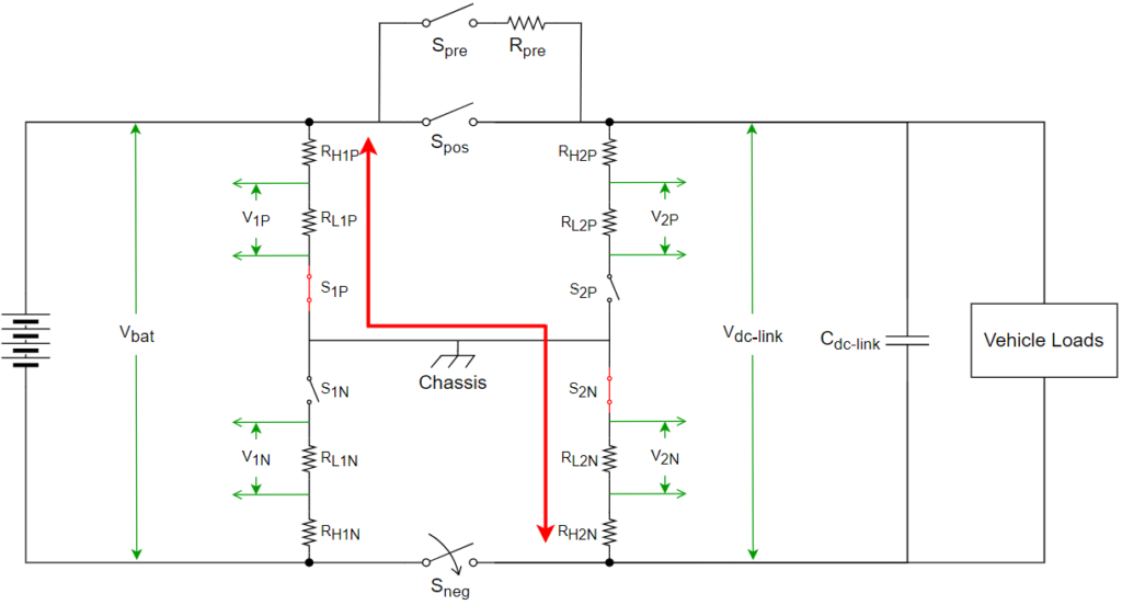
- Measure the voltage across the Sneg contactor, from the positive terminal of the battery to the negative terminal of the DC link.
- If the measured voltage equals the battery voltage, the contactor is closed with no indication of being stuck open.
- If the measured voltage is very low (ideally 0V), it signals that the Sneg contactor has not closed, indicating a stuck open condition.
Other Contactors:
- Repeat the process for other contactors by individually requesting them to close.
- Measure the voltage across each contactor to detect stuck open conditions.
- A low measured voltage indicates a stuck open contactor.
Detection of Stuck Closed Contactors:
The detection of stuck closed contactors involves the process of initiating the opening of each contactor individually and measuring the voltage at specific points. Here’s the step-by-step procedure:
Sneg Contactor:
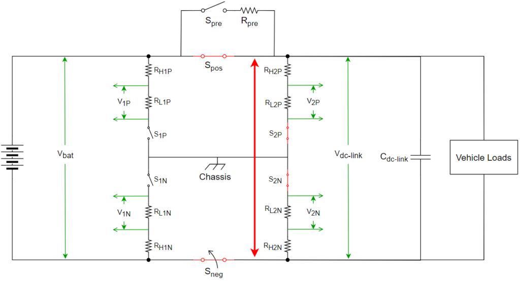
- Request the Sneg contactor to open while keeping the Spos contactor closed.
- Measure the voltage at the DC link side.
- If the DC link voltage reduces to a low level (ideally 0V), the negative contactor is open with no stuck closed condition.
- If the DC link voltage remains equal to the battery voltage, it indicates that the Sneg contactor has not opened despite the request, suggesting a stuck closed condition.
Spos Contactor:
Request the Spos contactor to open when the Sneg contactor is already open.
Measure the voltage from the positive terminal of the DC link to the negative terminal of the battery.
If the voltage reduces to a low level (ideally 0V), the Spos contactor is open with no stuck closed condition.
If the DC link voltage remains equal to the battery voltage, it suggests that the Spos contactor has not opened despite the request, indicating a stuck closed condition. By employing these detection methods, potential issues with stuck open or stuck closed contactors can be efficiently identified, facilitating timely corrective actions in HV systems.
Voltage Measurement Process/Technique:
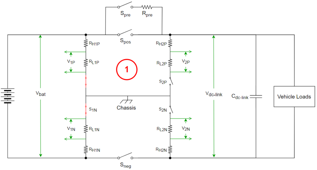
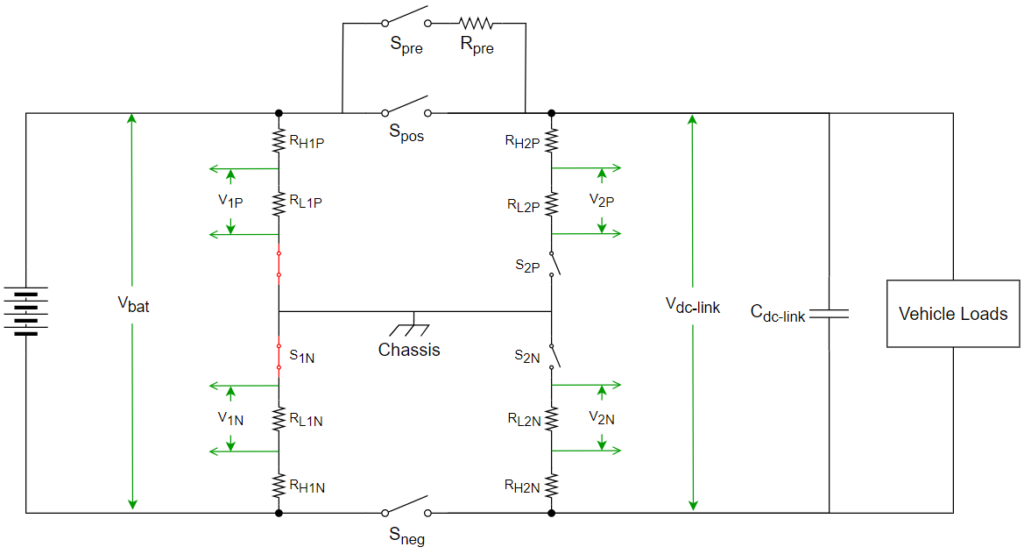
To measure voltage in the HV system, resistor divider circuits are used as illustrated in the following picture. The circuit configuration is controlled by switches S1P, S2P, S1N, and S2N, allowing the connection or disconnection of the resistors as required.
Let’s consider the example of measuring the HV battery voltage (Vbat):
- Close switches S1P and S1N.
- Measure voltages V1P and V1N.
Both V1P and V1N represent the battery voltage. However, for enhanced accuracy, the average of these measurements is calculated using the following formula:
- Vbat (with V1P) = Vbat1 = V1P * (RH1P + RH1N + RL1P + RL1N) / RL1P
- Vbat (with V1N) = Vbat2 = V1N * (RH1P + RH1N + RL1P + RL1N) / RL1N
- Vbat = (Vbat1 + Vbat2) / 2.
By systematically manipulating the measurement switches (S1P, S2P, S1N, and S2N), voltages can be accurately measured at the DC link and across the contactors, facilitating precise monitoring and control of the HV system.
EV Charging Explained – Everything you need to know about Electric Vehicle Charging