Inside an AC EVSE: Exploring the Components within an AC EVSE
To gain a deeper understanding of the content in this article, kindly refer the following articles first:
History of Electric Vehicle Charging – EV Charging Explained
Introduction to EV Charging: A Beginner’s Guide – EV Charging Explained
What is an AC Charging Station or AC EVSE?
An AC Charging Station, or AC Electric Vehicle Supply Equipment (AC EVSE), serves as a crucial intermediary between electric vehicles (EVs) and the AC grid, ensuring a safe and controllable connection. Despite being colloquially called a “charging station,” it doesn’t directly charge the vehicle; rather, it functions as an essential connection device facilitating the interface between the EV and the AC grid.
Why is an AC EVSE Needed?
AC EVSE is needed for providing the AC supply to EV in a safe and controlled manner. If EV is directly connected to a home socket, then EV does not know the power rating of the socket. If EV draws higher currents than socket rating, it can create a fire hazard. To avoid this situation, AC EVSE will communicate the maximum possible charging current to EV during the charging process.
More details can be found at the “1.3. Mode-3 Charging: (AC Charging)” section in Introduction to EV Charging: A Beginner’s Guide – EV Charging Explained
Overview of the Components Inside the EVSE:
The image below provides a glimpse into the components housed within an AC EVSE.
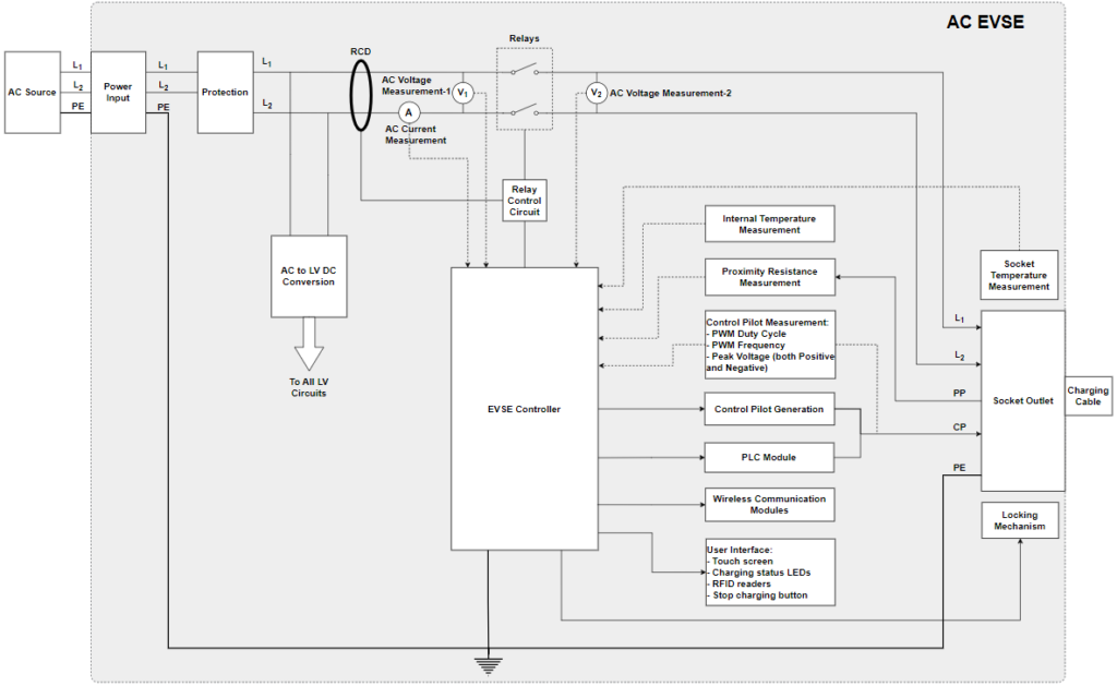
Further details on each specific component inside the EVSE and their functionalities are provided in the subsequent sections.
Power Input:
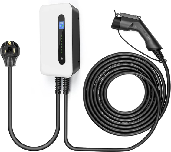
The Power Input in an AC EVSE is the portal through which the EVSE connects to the external AC power source. Two primary methods exist for this connection:
- Connecting through a Plug: While this method is straightforward, it is not the preferred choice due to the potential for overheating if the plug and sockets are not adequately rated for the required power levels. Overheating can lead to safety hazards and equipment damage.
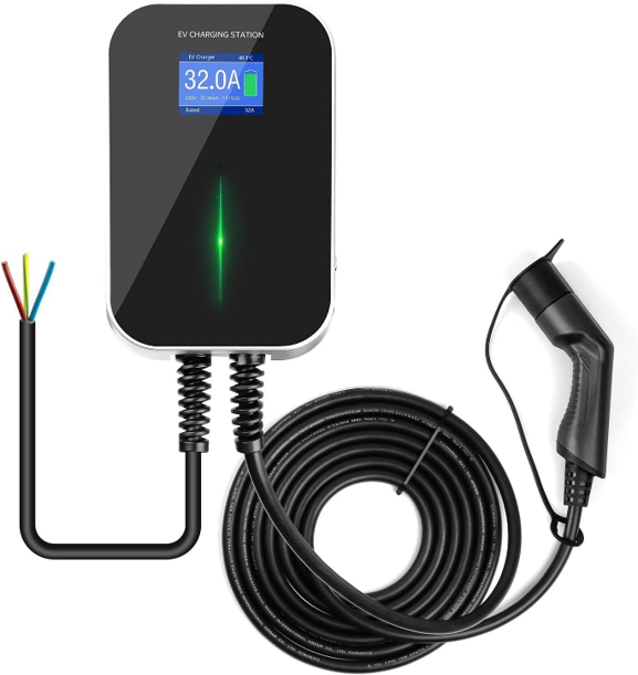
- Connecting the Cable Directly to the Mains: This is the recommended approach as it mitigates the risk of plug and socket overheating. Directly connecting the cable to the mains provides a more stable and secure power connection, reducing the likelihood of electrical issues during the charging process.
Protection:
Protection mechanisms are crucial for ensuring the safety and reliability of the AC EVSE. These mechanisms safeguard the EVSE and the EV from various scenarios:
- Grid Disturbances: Protection devices such as surge protection device (SPD) or transient voltage surge suppressor (TVSS) are in place to handle grid disturbances such as voltage transients, over voltages, and under voltages. These disturbances can occur due to fluctuations in the power grid, and protection mechanisms prevent potential damage to the charging system.
- Overcurrent Protection: Fuses and circuit breakers play a vital role in protecting the system from overcurrent scenarios, particularly in the event of a short circuit. These devices interrupt the circuit if the current exceeds safe limits, preventing damage to the EVSE and the connected EV.
Residual Current Device (RCD):
Residual Current Device (RCD), is a device designed to quickly disconnect electrical circuits when it detects an imbalance in the electric current flowing through the circuit. The imbalance typically indicates a leakage of current to the ground, which could be potentially dangerous. RCDs play a crucial role in electrical safety by helping to prevent electric shocks and fires.
RCDs are linked to relay control circuits so that in case of leakage current detection, AC relays are automatically opened.
Different types of RCDs cater to specific needs as mentioned below:
- Type AC RCD:
- Functionality: This type of RCD is designed to detect and respond to AC faults.
- Applications: Suitable for general-purpose use in residential and commercial environments where the load primarily consists of devices using standard alternating current.
- Type A RCD:
- Functionality: Type A RCDs are more advanced than Type AC RCDs. They not only detect AC faults but also provide additional sensitivity to pulsating DC faults.
- Applications: Recommended for environments where electronic devices with electronic components may cause pulsating DC leakage currents, such as in homes with modern appliances.
- Type F RCD:
- Functionality: Type F RCDs are designed to be even more sensitive and versatile. They can detect AC and pulsating DC faults, as well as smooth DC faults.
- Applications: Ideal for applications where electronic equipment with variable speed drives or frequency converters is present. Type F RCDs are often used in industrial and commercial settings where the load includes sophisticated electronic devices.
- Type B RCD:
- Functionality: Type B RCDs are the most advanced and comprehensive, capable of detecting and responding to AC, pulsating DC, and smooth DC faults. They provide a high level of protection against a wide range of potential electrical faults.
- Applications: Typically used in specialized environments with specific and demanding electrical requirements, including medical facilities, laboratories, and places with complex electrical loads.
As per the standards, AC EVSEs must be equipped with at least Type-A RCD functionality to ensure robust electrical safety. This is becuase, On-Board Chargers (OBCs) in EVs are electronic components and they can cause DC leakage current during charging.
AC Relays and Control Circuit:
AC Relays and their control circuits play a crucial role in managing the connection and disconnection of the electric vehicle to the AC power source. These components ensure a controlled and safe power flow during the charging process.
AC to LV DC Conversion:
The AC to Low Voltage (LV) DC conversion is a pivotal step in the EVSE. This conversion transforms the incoming AC power from the grid into low-voltage DC suitable for powering the various low-voltage circuits within the EVSE. The typical output voltage is either 12V or 5V or both, depending on the design of the low-voltage circuits.
Socket Outlet and Locking Mechanism:
- Socket Outlet: In scenarios where a detachable charging cable is required (EVSEs which support Type-2 and GBT AC), a socket outlet becomes integral. This outlet provides the physical interface for connecting the charging cable to the EVSE.

- Locking Mechanism: If Socket outlet is present, then the locking mechanism ensures the secure attachment of the charging cable during the charging process. This feature prevents accidental removal, reducing the risk of arcing and damage to connector pins. Additionally, it serves as a deterrent against cable theft.
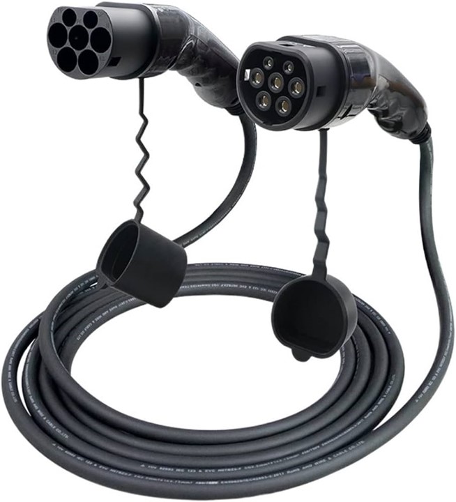
Charging Cable:
Charging cables are a critical link between the EVSE and the electric vehicle. The choice between a permanently connected or detachable charging cable depends on factors such as the EVSE type and design considerations.
- Permanently Connected Cable: Common in EVSEs with Type-1 charging cables, this configuration involves a fixed, hardwired connection between the charging cable and the EVSE.

- Detachable Charging Cable: Common in EVSEs with Type-2 and GBT AC charging cables, this configuration allows users to connect and disconnect the charging cable as needed, offering greater flexibility. These cables are equipped with a proximity resistance to indicate their current carrying capacity (More details cab be found in the following proximity resistance measurement section).
EVSE Controller:
The EVSE Controller serves as the central control unit (with a Micro Controller), managing and coordinating all functionalities of the EVSE. It acts as the intelligent hub, ensuring the seamless and efficient operation of the charging process.
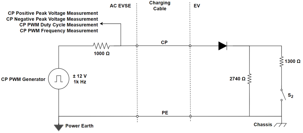
Control Pilot PWM Generation:
The Control Pilot PWM generation system is responsible for generating the Pulse Width Modulation (PWM) signal used for communication between the EVSE and the EV. This communication is essential for coordinating the charging process.
The Control Pilot (CP) PWM parameters (as per IEC 61851-1) include:
- PWM frequency: 1kHz
- PWM duty cycle:
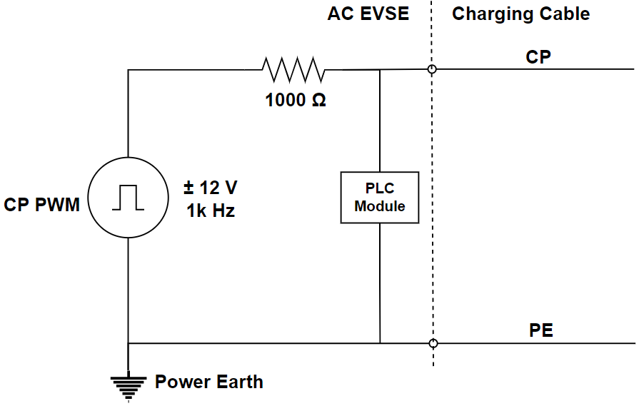
- In case of EVSE supporting the PLC communication: 5%
- In case of no PLC communication (it is called basic PWM): 10% to 96% depending on the current limit of the EVSE
- CP PWM peak voltage:
- Positive peak voltage: +12V
- Negative peak voltage: -12V

CP is used to convey the different EVSE parameters to EV. Below is a list of the diverse functions encapsulated by the CP:
| CP PWM Positive Peak Voltage | CP PWM Negative Peak Voltage | CP PWM Duty Cycle | Interpretation of EVSE status/parameters |
| 0 | 0 | 0% | Typically, this condition arises due to an error, such as: – Absence of power to the EVSE, as seen in an AC voltage outage. – A short circuit occurring between the control pilot and the protective conductor. |
| +12V | 0 | 100% | EVSE is not ready to deliver the power because of any internal limitations (may be internal over temperature of the EVSE) |
| 0 | -12V | 100% | The EVSE deliberately establishes this state to indicate a fault condition, such as the requirement for maintenance of the EV supply equipment. |
| +12V | -12V | 5% | PLC communication is required to exchange the data between EVSE and EV |
| +12V | -12V | 10% – 96% | As per IEC 61851-1, duty cycle corresponding to EVSE maximum current limit is as below: – for 10% to 85%, CP PWM duty cycle = (EVSE maximum current limit / 0.6) – for 85% to 96%, CP PWM duty cycle = (EVSE maximum current limit / 2.5) + 64 |
PLC Module:
Power Line Communication (PLC) module enables the data transmission over the CP line. PLC facilitates effective communication between the EVSE and the EV for data exchange.
Wireless Communication Modules:
Wireless communication modules provide additional connectivity options, allowing the EVSE to communicate with external networks. These modules support remote monitoring, firmware updates, and may facilitate payment transactions in commercial or public charging stations.
Measurements:
The key measurements include:
- AC Current Measurement: The AC current is measured, serving various essential functions:
- If the current drawn from the EV exceeds the communicated EVSE current limit, then EVSE triggers the opening of relays as a protective measure.
- Along with AC voltage measurements, the current is utilized for energy metering, accurately calculating the energy consumed by the EV during the charging session.
- AC Voltage Measurement: AC voltage is measured both before and after the relays, contributing to multiple functions:
- Energy metering, providing insights into the consumption patterns of the EV during charging.
- Detection of welding issues in the relays.
- Identification of over voltages and under voltages, allowing the EVSE to respond proactively to fluctuations in the power supply.
- Socket Outlet Temperature Measurement: Monitoring the temperature of the socket outlet to detect potential overheating issues. This measurement serves as an early warning system to prevent hazards related to excessive temperatures at the charging point.
- Internal Temperature of the EVSE Measurement: Strategic measurement points within the EVSE are dedicated to monitoring internal temperatures. This helps identify any areas prone to overheating, allowing for timely interventions and preventive measures.
- CP PWM Related Measurement: Various aspects of the CP PWM signal are measured, including:
- CP PWM Duty Cycle
- CP PWM Frequency
- CP Positive and Negative Peak Voltage: These measurements play crucial roles in ensuring effective communication between the EVSE and the electric vehicle, contributing to the coordination and control of the charging process.

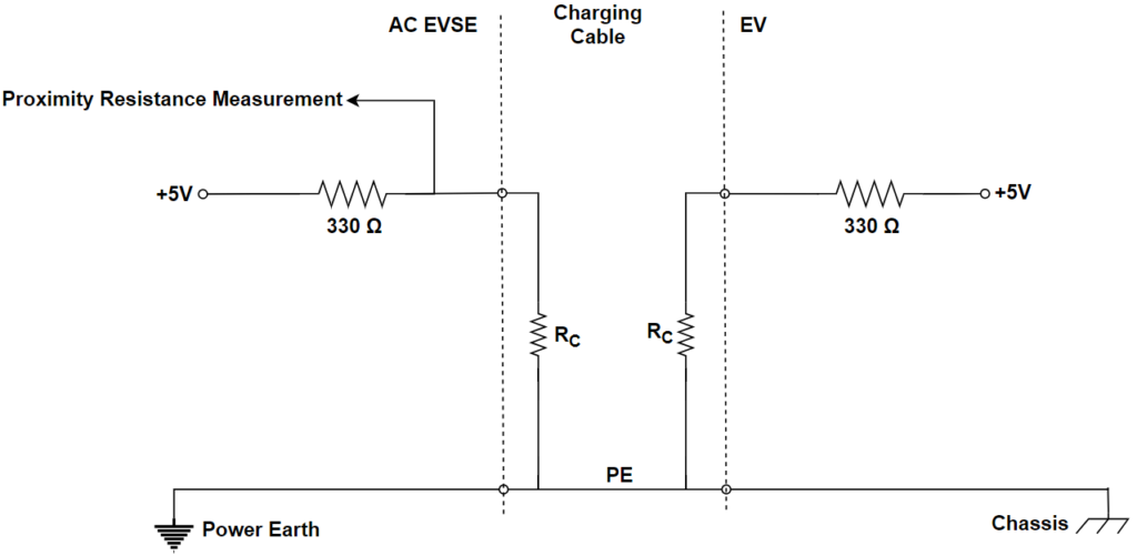
- Proximity Resistance Measurement: Proximity resistance is measured for essential functionalities:
- Detection of the connection of the charging cable to the socket outlet.
- Determination of the current limit of the charging cable, providing insights into the capacity of the cable and ensuring safe charging practices.
* Same Proximity Resistance (RC) is placed inside the charging cable on both EV and EVSE sides.
| Proximity Resistance (RC) (As per IEC 61851-1) | Current Carrying Capacity of the Charging Cable |
| 1500Ω | 13A |
| 680Ω | 20A |
| 220Ω | 32A |
| 100Ω | 63A |
User Interface:
The User Interface is the portal through which users interact with and control the charging process. It includes various components to enhance user experience:
- Touch Screen: An intuitive touch screen provides users with a user-friendly interface for controlling and monitoring the charging process.
- Charging Status LEDs: LEDs or displays inform users of the current charging status, offering visual cues for the progress of the charging session.
- RFID Readers: RFID readers enable user authentication and access control. Only authorized users with the appropriate RFID credentials can initiate the charging process.
- Buttons: Physical buttons provide users with additional control options, allowing them to start or stop the charging process and adjust settings as needed.
Overview of the Charging Sequence:
Initiating the charging process of an Electric Vehicle (EV) through an AC Electric Vehicle Supply Equipment (EVSE) involves a systematic sequence of steps aimed at ensuring a secure and regulated charging experience. Here is an overview of the typical steps from the initiation to the completion of the charging process:
1. Authentication and User Identification:
Users may need to authenticate themselves using features like RFID readers before initiating the charging process. This step helps manage access to the charging station, particularly in public or commercial charging scenarios. Until the user is identified, the EVSE signals its not-readiness with a CP duty cycle of 100% and +12V.
2. Charging Cable Connection to EVSE:
If the EVSE is equipped with a socket outlet, users connect the charging cable to the EVSE. The EVSE detects the cable by measuring proximity resistance. Once the cable is connected and the user is authenticated, the EVSE signals its readiness with CP PWM duty cycle corresponding to the current limit. Additionally, the charging cable is locked in place.
3. Charging Cable Connection to EV:
- Users connect the charging cable to the EV and EV measures the proximity resistance to confirm the charging cable connection; and measures the CP PWM parameters to understand EVSE readiness and current limits.
- The EVSE detects the cable connection to EV by measuring the CP PWM positive peak voltage, changing from +12V to +9V.
4. Communication Initiation:
- If the EVSE supports PLC which is indicated by a CP PWM duty cycle of 5%, the EV initiates communication and exchange information about capabilities and current limits of EV and EVSE.
- Without PLC, the EVSE informs the maximum charging current limit through CP PWM duty cycle, and there is no exchange of information from the EV side.
5. Indication of EV Readiness to Receive Power:
The EV evaluates the EVSE’s current limit and checks for vehicle readiness. If there are no concerns to start charging, it closes the S2 switch, indicating EV readiness.
6. Relay Closing in EVSE:
The EVSE detects the closed S2 switch by measuring CP PWM positive peak voltage changing from +9V to +6V. It then closes the relays, providing AC voltage to the EV.
7. Charging the HV Battery:
With AC voltage available, the On-Board Charger (OBC) in the EV begins charging the High-Voltage (HV) battery within the limits communicated by the EVSE.
8. Charging Session Monitoring:
The EVSE continuously monitors parameters like current, voltage, and temperatures throughout the charging session, responding promptly to any anomalies or safety concerns.
9. Charging Completion and Termination:
- If the EV wishes to stop charging (due to a fully charged HV battery or user request), it opens the S2 switch. The EVSE detects this change and opens the AC relays.
- If the EVSE initiates the stop charging, it changes the CP duty cycle to 100%, and the EV detects this change, stopping the charging process.
10. Charging Cable Disconnection:
After the charging session concludes, users safely disconnect the charging cable from the EV and, if necessary, from the EVSE.
11. User Interface Display:
The EVSE’s user interface, equipped with features like a touch screen or LEDs, displays relevant information about the charging session, including status and energy consumption, keeping users informed.
By meticulously following these steps, the AC EVSE ensures a seamless, secure, and controlled charging experience for electric vehicle users.
In conclusion, the AC EVSE is a complex system composed of meticulously designed components, each playing a specific role in ensuring the safe, controlled, and user-friendly charging of EVs. As the demand for EVs continues to grow, the importance of robust and intelligent AC EVSE systems becomes increasingly evident in shaping the future of sustainable transportation.
EV Charging Explained – Everything you need to know about Electric Vehicle Charging