History of Electric Vehicle Charging: A Journey Through Evolution of Electric Vehicle Charging
Electric Vehicle (EV) charging, a crucial aspect of the electric mobility revolution, has witnessed a fascinating evolution over the years. From the humble beginnings of non-rechargeable batteries to sophisticated on-board chargers and the emergence of standardized charging systems reflect the relentless innovation in the electric mobility sector.

Early 19th Century: EVs with Disposable Batteries
In the early 19th century, the batteries powering EVs were non-rechargeable. Once depleted, these disposable batteries were discarded, and the concept of recharging was nonexistent.
Mid to End of 19th Century: EVs with Rechargeable Lead-Acid Batteries
The breakthrough invention of rechargeable lead-acid batteries in the mid-19th century transformed the landscape of EVs. Now, newer electric car models could utilize the same batteries repeatedly, eliminating the need for frequent replacements.
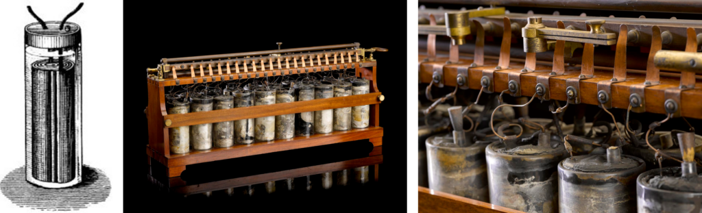
Source: https://collection.sciencemuseumgroup.org.uk/objects/co36401/one-of-the-first-rechargeable-batteries-about-1860-batteries
Charging these early lead-acid batteries was a manual process. Batteries were charged by connecting the battery to a Direct Current (DC) power source. This power source is a DC dynamo/generator, often driven by a steam engine. Even though there isn’t clear information regarding how the voltage at the battery terminals was regulated, it might have been accomplished through two potential methods: one involved controlling the output voltage of the DC power source by changing the speed of the power source, while the other method is by adjusting the series resistance. Voltage levels at the battery terminals was systematically raised until the battery is fully charged.


Operators played a crucial role in this charging process, manually adjusting the charging current and voltage to prevent overcharging and potential damage to the battery. Sophisticated charging controllers, commonly found in contemporary charging systems, were not present during this era.
A curious fact emerges from this era: Why were DC generators preferred over AC generators? The answer lies in the fact that the loads in existence were designed for DC voltage. In the early days, loads such as lights and DC motors were designed based on the DC voltage from non-rechargeable batteries. So, as generators were invented, they were naturally designed for DC generation (using a commutator) to support the existing loads.
Early 20th Century: The rise of EVs and the Inception of Public Charging Infrastructure
In the early 20th century, electric cars experienced a peak in popularity, making up 38% of the total U.S. automobile market share. Steam-powered vehicles constituted 40%, while gasoline-powered ones made up 22%. In the United States, a substantial fleet of 33,842 electric cars operated during this period. Electric cars of this time were charged either when the batteries are on-vehicle or batteries were taken off the vehicles and charged at designated facilities called “Battery Rooms”, and then installed back into the vehicle.


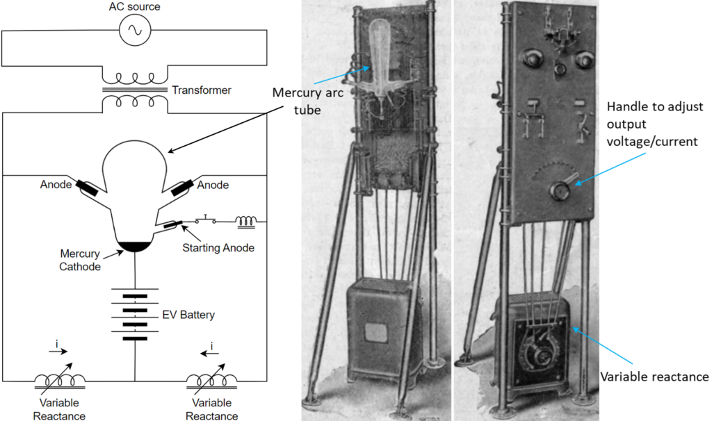
The 6kW Wattstation, introduced in the 1910s, stands as a pioneering prototype in the world of charging technology, marking a significant milestone in the early days of electric mobility. Equipped with cutting-edge technology for its time, the 6kW Wattstation used the mercury arc rectifier to convert alternating current (AC) to DC.
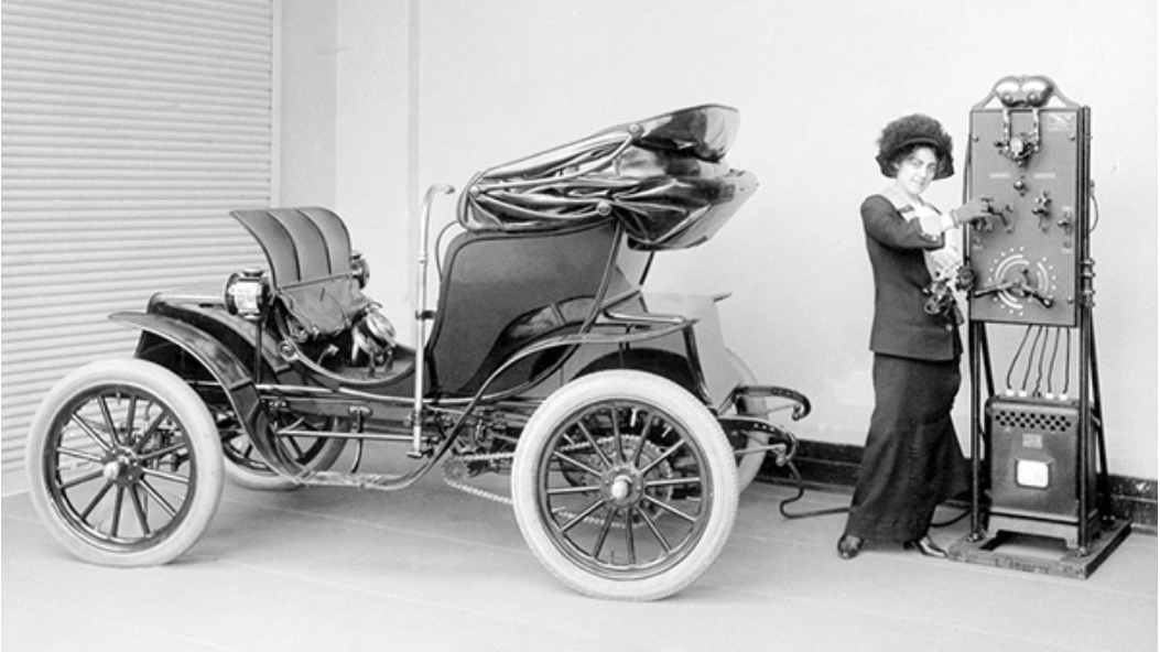
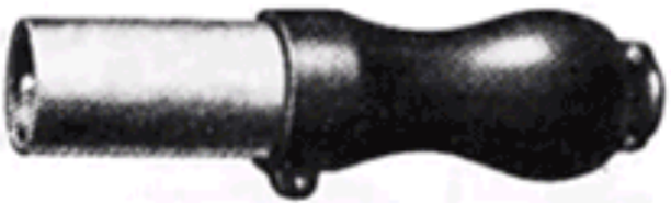
In 1914, General Electric introduced the first public DC charging station, the “Electrant” which also uses the mercury arc rectifier to convert AC to DC, positioned at accessible locations in major cities, these stations aimed to charge tens of thousands of electric cars. Notably, they utilized a separate billing system and could provide up to 150 amps to charge 48 V lead-acid batteries. The charging connector utilized a single-cell coaxial connection, with the center hole serving as the positive terminal for DC, while the surrounding shell functioned as the negative terminal for DC.
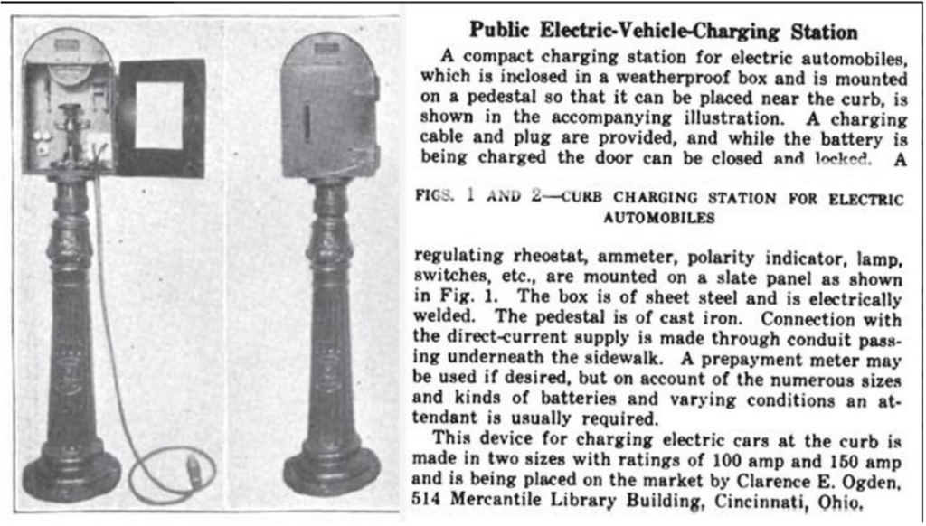

The process of charging batteries at these mercury arc rectifier stations requires manual intervention. After connecting the batteries to the rectifier’s output, the charging voltage/current is regulated by manually adjusting the variable reactance using a handle as shown in below picture. Operators would adjust the charging voltage/current manually to prevent overcharging and potential damage to the battery, ensuring a meticulous and controlled charging procedure.
Interesting fact: What prompted the necessity of mercury arc rectifiers, a component that wasn’t required in the mid-19th century to charge the batteries?
In the mid-19th century, DC dynamos were utilized for lead-acid battery charging. However, as AC power systems became widely adopted by the early 1900s, the requirement emerged for rectifiers to convert AC to DC. Thanks to Nikola Tesla for winning over Edison in the ‘AC vs DC battle’ and establishing the AC power system.
Operation of Mercury Arc rectifier:
Operation of the rectifier relies on an electrical arc discharge between electrodes in a sealed envelope containing mercury vapor at very low pressure. A pool of liquid mercury acts as a self-renewing cathode and Carbon is used as Anode. The mercury emits electrons freely, whereas the carbon anodes emit very few electrons even when heated, so the current of electrons can only pass through the tube in one direction, from cathode to anode, which allows the tube to rectify AC to DC. During this process, the mercury ions emit light, and the light appears pale blue-violet and contains much ultraviolet light.
Initiation of a typical mercury-arc rectifier involves a brief high-voltage arc within the rectifier, occurring between the cathode pool and a starting electrode. The starting electrode contacts the pool, enabling the passage of current through an inductive circuit. Subsequently, the contact with the pool is intentionally broken, resulting in a high voltage and the initiation of an arc discharge. Once the arc is initiated, it is sustained because of the input AC voltage.


Images source: https://www.electricstuff.co.uk/mercarc.html
Mid to Late 20th Century: Emergence of On-Board Chargers (OBCs)
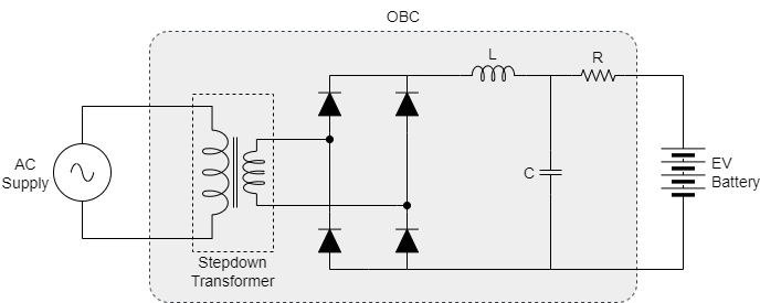
Prior to the introduction of solid-state rectifiers in the 1950s, the very concept of on-board chargers (OBCs) did not exist. This was primarily due to the impractical size of mercury arc rectifiers or vacuum tube rectifiers, making it impossible to accommodate AC-DC conversion circuits within vehicles. Consequently, AC to DC conversion was done externally, and DC power was directly utilized to charge the EV batteries.
The invention of the solid-state rectifier (with diodes) by Russell Ohl in 1940 marked a pivotal moment. Silicon-based diodes became popular for rectification, offering a more compact and reliable solution. This breakthrough enabled the feasibility of OBCs, significantly enhancing the convenience of at-home charging. Notably, the cost of OBCs was considerably lower compared to DC chargers featuring mercury arc rectifiers or vacuum tube rectifiers.
Several early EVs equipped with OBCs include the Henney Kilowatt (1959-1960, featuring 36 V and 72V lead-acid batteries), Enfield 8000 (1973, with 48V lead-acid batteries), and Sebring-Vanguard Citicar (1974, powered by 36V and 48V lead-acid batteries). Although the exact ratings of the OBCs used in these vehicles are unclear, they likely ranged between 3 kW to 6 kW, facilitating overnight battery charging.
Late 20th Century Onwards: Semiconductor Revolution and DC Fast Charging
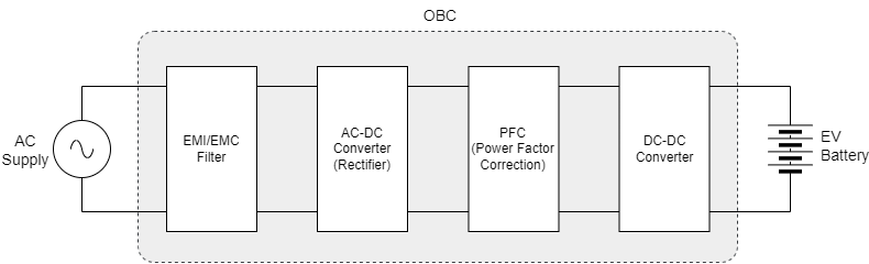
The revolution in semiconductor devices and the advent of digital electronics, particularly integrated circuits, from the 1970s paved the way for sophisticated control systems. Pulse-width modulation (PWM) techniques gained prominence, offering precise control over output voltage and current. This era witnessed notable advancements in power electronics, characterized by the integration of digital control and feedback systems, resulting in more compact and efficient OBCs.
Early vehicles showcasing advanced power electronics in their OBCs include:
- General Motors EV1 (1996):
- Battery: 16.5–18.7 kWh lead–acid, 312V; 26.4 kWh nickel–metal hydride (NiMH), 343V
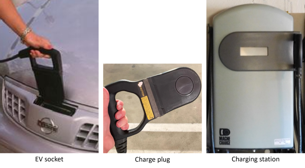
- OBC: 6.6 kW using Magne Charge connector.
- Toyota RAV4 EV (1997):
- Battery: Panasonic 27.4 kWh NiMH, 288V
- OBC: 6 kW using Magne Charge connector.
From this period onward, OBCs became a standard integral component in all EVs, emphasizing their crucial role in advancing electric mobility.
Emergence of DC Fast Chargers: Overnight home charging using OBCs suits short commutes where frequent recharging isn’t necessary. However, this falls short of making EVs as practical as internal combustion engine (ICE) vehicles for daily and long-distance use. Achieving practicality similar to ICE vehicles demands faster refueling times and long-distance travel capability. Placing high-power chargers (>50kW) within the vehicle is impractical because of their size and weight. Thus, the emergence of dedicated DC fast chargers has become crucial. These chargers provide competitive charging times for EVs, making them a viable alternative to ICE vehicles. Positioned strategically in cities and along highways, akin to traditional fuel stations, DC fast chargers enable versatile EV usage for various situations, ensuring practicality for daily commuting, extended journeys, and diverse purposes.
Evolution of EV Charging Standards: From Magne Charge to Modern Standardization (1990s Onward)
1990s onward, as the EV industry began to gain momentum, the need for standardized charging systems became increasingly apparent. The surge in electric mobility prompted stakeholders to address challenges related to interoperability, user convenience, market growth, and safety. Charging standards, in essence, refer to a set of agreed-upon guidelines and protocols governing how EVs are charged. These standards encompass physical connectors, communication protocols, power levels, and safety features. They serve as the foundation for a harmonized and efficient charging infrastructure, essential for the sustainable growth and acceptance of EVs globally.
The following is a compilation of EV charging standards:
1. Magne Charge (1990s – Early 2000s) – AC Standard:
It is a high-frequency inductive charging, developed in accordance with the SAE standard J1773. Primarily used for vehicles like GM EV1, Chevy S10 EV, Nissan Altra, and 1st gen Toyota RAV4 EV. It became obsolete by 2003 with no new vehicles incorporating it. This standard supported 1-phase 120V-240V AC charging.
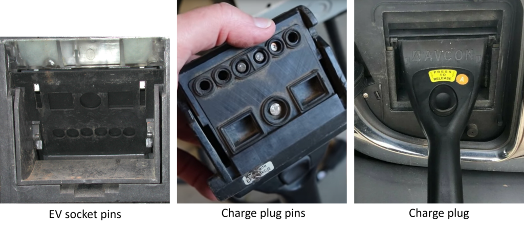
2. J1772 Avcon Connector (2006 – 2010) – AC Standard:
The California Air Resources Board (CARB) opted for conductive coupling over inductive technology (Magne Charge) for recharging EVs, adopting the SAE J1772-2001 standard in 2001. Avcon produced the initial rectangular connector capable of 6.6 kW and used until 2010, mainly in the USA. This standard supported 1-phase 120V-240V AC charging but it was discontinued because of the adoption of J1772 Yazaki Connector.
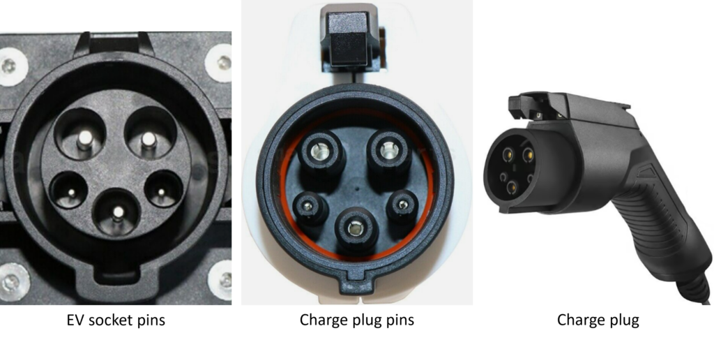
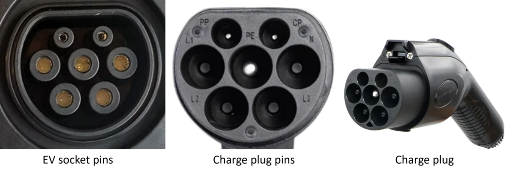
3. J1772 Yazaki Connector (IEC 62196 Type 1) (2010 – Present) – AC Standard:
CARB sought higher current delivery than J1772 Avcon Connector, leading to Yazaki’s round connector design (up to 19.2 kW). It supports 1-phase 120V-240V AC charging. Mandated by CARB in 2008 for 2010 models, it is mainly used in North America and few other countries worldwide.
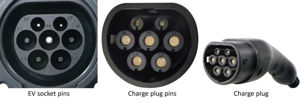
4. IEC 62196 Type 2 (2013 – Present) – AC Standard:
IEC 62196 Type 2, or Mennekes connector, is a prevalent European standard. It supports 1-phase and 3-phase AC charging. Adopted by the EU, this standard is used within Europe, Australia, and few other regions worldwide.
5. IEC 62196 Type 3 (1999 – 2013) – AC Standard:
Mainly utilized in France and Italy, Type 3 connectors (3A and 3C) were replaced by Type 2 in 2013 as mandated by the European Union. Type 3A supported 1-phase charging from 1999 to 2013, while Type 3C supported both 1-phase and 3-phase AC charging from 2010 to 2013.

6. GB/T AC (GB/T 20234.2) (2011 – Present) – AC Standard:
Developed by China, this standard has gained widespread adoption within the country. Initially, until 2015, it exclusively supported 1-phase AC charging. However, with the revision of the standard in 2015, it expanded its compatibility to encompass both 1-phase and 3-phase AC charging.
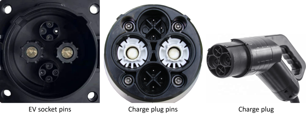
7. CHAdeMO (2010s – Present) – DC Standard:
CHAdeMO, introduced in Japan in the 2010s, is a pioneering DC fast charging standard that gained global recognition. Initially employed across multiple countries, it served as the first standard until region-specific alternatives were established. CHAdeMO’s first-generation connectors supported up to 62.5 kW and the second-generation connector allows an impressive 400 kW. Currently, it continues to be prominently utilized in Japan.
8. GB/T DC (GB/T 20234.3) (2011 – Present) – DC Standard:
Developed by China, this stands out as a prominent high-power DC charging standard within the country, capable of supporting up to 250 kW.
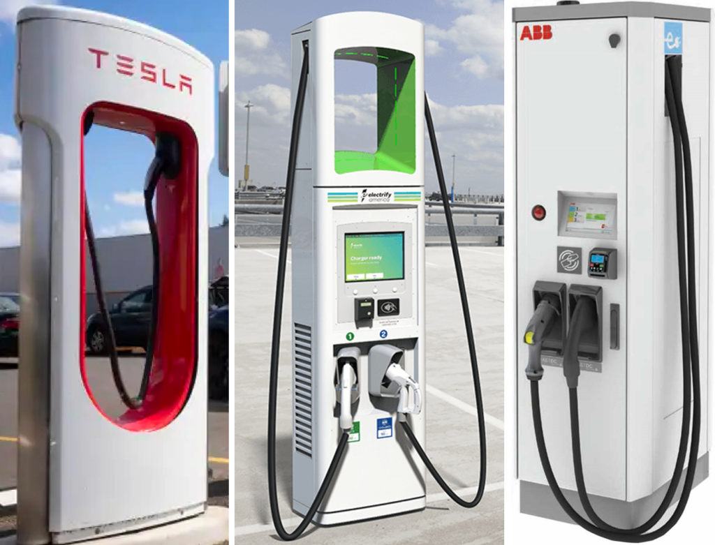
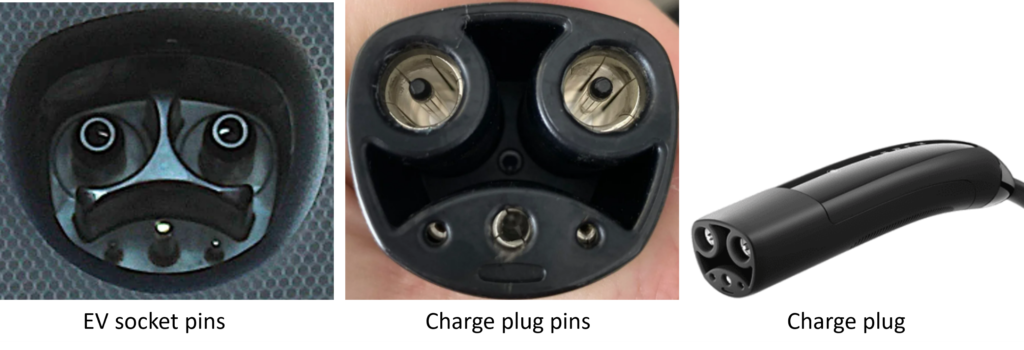
9. NACS (2012 – Present) – AC & DC Standard:
The North American Charging Standard (NACS), or Tesla charging standard, developed by Tesla, Inc., has been used in all North American Tesla vehicles since 2012. In 2022, Tesla opened its use to other manufacturers. This standardized system features a single-plug connector supporting both AC and DC charging with identical power pins, accommodating single-phase AC charging and high-power DC charging.
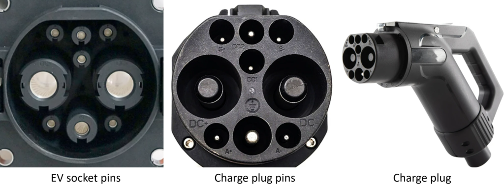
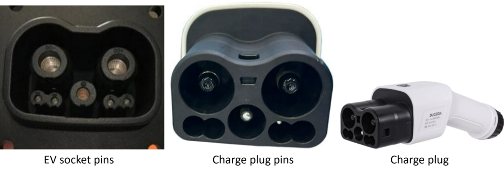
10. CCS1 (2013 – Present) – AC & DC Standard:
CCS1 (Combined Charging System 1) lives up to its name by combining both AC and DC charging capabilities within a single connector. It features a J1772 (IEC 62196 Type 1) socket for AC charging and incorporates dedicated pins for high-power DC charging. With a notable capacity, it supports a DC charging power of up to 350 kW. This standard is predominantly utilized in North America.

11. CCS2 (2013 – Present) – AC & DC Standard:
Similar to CCS1, CCS2 (Combined Charging System 2) seamlessly combines AC and DC charging functionalities within a single connector. Equipped with an IEC 62196 Type 2 socket for AC charging and dedicated pins for high-power DC charging, it boasts a substantial capacity, supporting up to 350 kW of DC charging power. This standard is widely used in Europe.

12. ChaoJi (Not in use yet) – DC Standard:
The ChaoJi connector, alternatively known as CHAdeMO 3.0, represents an ultra-high-power DC charging standard for EVs. Unveiled in 2020, it has the capability to support up to 900 kilowatts. This standard is a joint development by Japan and China.
Conclusion
In conclusion, the evolution of EV charging stands as a testament to the continuous innovation and technological advancements in the electric mobility sector. From the humble beginnings of non-rechargeable batteries in the early 19th century to the sophisticated and standardized charging systems of today, the journey has been marked by significant milestones.
One response to “History of Electric Vehicle Charging”
-
Great article Amar. A combination of history and science. Well explained with relevant collections of pictures and diagrams.
EV Charging Explained – Everything you need to know about Electric Vehicle Charging
Great article Amar. A combination of history and science. Well explained with relevant collections of pictures and diagrams.