Charging Control in Multi-Pack Parallel Connected Batteries for EVs
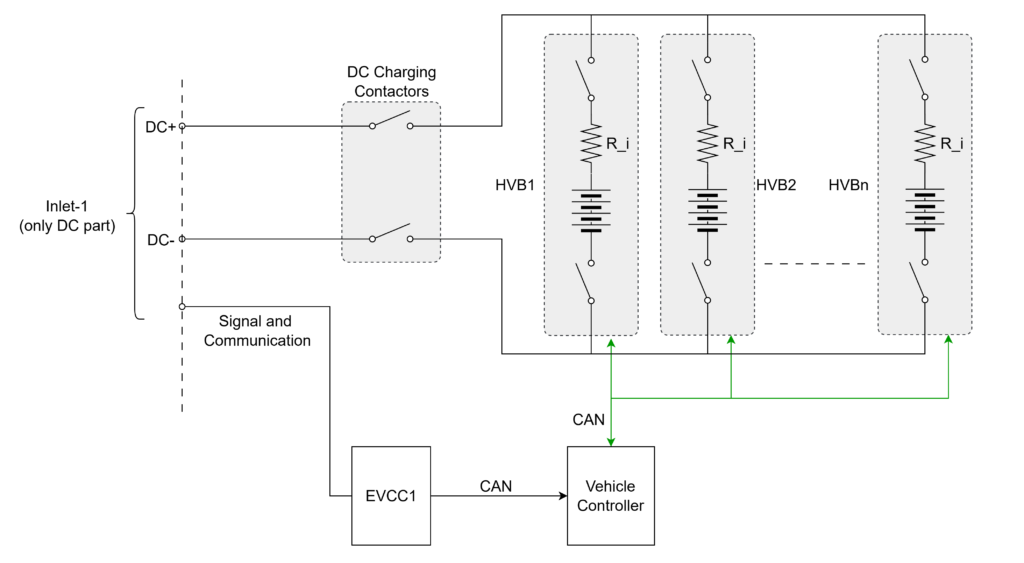
Electric vehicles (EVs), especially commercial vehicles such as trucks, buses, and delivery vans, demand high energy and power to operate over long distances or under heavy loads. To meet these energy requirements, multiple battery packs are often connected in parallel. However, managing such a system is complex. If all batteries are permanently connected to the DC bus, a fault in one pack can halt the entire vehicle. This poses a serious threat to the uptime of commercial vehicles. For instance, logistics fleets operating on tight schedules or city buses providing regular service cannot afford unplanned downtime due to battery pack faults. Hence, battery pack isolation becomes a key enabler for operational continuity. To mitigate this risk, battery packs are connected to the DC link via individual contactors. This way, a faulty pack can be isolated while the rest continue operating.
Challenges in Multi-Pack Battery Systems
- Voltage Imbalance:
- Over time, batteries develop voltage imbalances due to differences in chemical characteristics and aging. No two batteries are chemically identical, leading to variations in State of Health (SOH) and internal resistance.
- Even if the packs operate under the same conditions, these differences cause uneven aging, which results in varying voltages over time.
- Over time, batteries develop voltage imbalances due to differences in chemical characteristics and aging. No two batteries are chemically identical, leading to variations in State of Health (SOH) and internal resistance.
- Uneven Current Sharing:
- Batteries with lower internal resistance tend to absorb or deliver more current during charging and discharging, respectively.
- For example, during charging, a battery with lower internal resistance will receive more current, while one with higher resistance will receive less. Conversely, during discharging, the low-resistance pack discharges more.
- This imbalance in current flow contributes further to voltage deviations.
- Batteries with lower internal resistance tend to absorb or deliver more current during charging and discharging, respectively.
- Inrush Currents:
- Directly connecting packs with voltage mismatches can lead to large inrush currents, which may damage the batteries or shorten their lifespan.
- These inrush currents must be managed carefully by controlling when and how the packs are connected.
- Directly connecting packs with voltage mismatches can lead to large inrush currents, which may damage the batteries or shorten their lifespan.
Control Strategy During Charging
- Initial Battery Selection:
- Charging starts with the group of batteries that have the lowest voltages. This prevents high voltage differences during initial connection.
- The Vehicle Control Unit (VCU) calculates estimated inrush current based on measured voltages and estimated/worst-case internal resistance values. (Example is given at following sections)
- If the inrush current is within safe limits (as specified by battery manufacturer), the identified group of batteries is connected to the DC link by closing their contactors.
- If no group matches closely, connect a single pack with the lowest voltage.
- Charging starts with the group of batteries that have the lowest voltages. This prevents high voltage differences during initial connection.
- Progressive Charging:
- Charging begins.
- As the voltages of connected packs rise, the VCU monitors if they match or come close to the voltages of other disconnected packs.
- When the voltage gap is sufficiently small, and the estimated inrush current is acceptable, the next group of batteries is connected.
- The charging current limit is dynamically adjusted depending on the number of packs connected.
- Charging begins.
- Completion:
- This process continues iteratively until all battery packs are connected and charged to the target SOC.
- The VCU coordinates this entire process by collecting data from Battery Management Systems (BMS) and executing control actions accordingly.
- This process continues iteratively until all battery packs are connected and charged to the target SOC.
Control Strategy During Discharging (Vehicle Operation)
- Initial Discharge:
- During vehicle operation, the discharge process starts with the battery or group of batteries with the highest voltage.
- The logic is similar to charging but in reverse, starting from the healthiest, most charged batteries.
- The VCU calculates the potential current sharing impact and verifies if the internal resistance and voltage levels support safe parallel operation.
- During vehicle operation, the discharge process starts with the battery or group of batteries with the highest voltage.
- Dynamic Engagement:
- As the highest-voltage batteries discharge and their voltages drop, the VCU evaluates the next suitable battery or group to engage.
- Again, inrush current calculations are made to prevent high current spikes.
- Once conditions are met, the VCU closes the contactors for the next group.
- As the highest-voltage batteries discharge and their voltages drop, the VCU evaluates the next suitable battery or group to engage.
- Sustained Operation:
- This process continues until the vehicle reaches its operational limit or all battery packs are evenly discharged.
- At every step, the VCU ensures the current is well distributed, and no battery is over-stressed.
- This process continues until the vehicle reaches its operational limit or all battery packs are evenly discharged.
Example: Inrush Current Estimation
Assume three battery packs with the following properties:
- Pack A: Voltage = 700V, Internal Resistance = 50 mΩ
- Pack B: Voltage = 710V, Internal Resistance = 45 mΩ
- Pack C: Voltage = 725V, Internal Resistance = 40 mΩ
- Manufacturer allowed inrush current = 150A
Now, assume Pack A is already connected and charging.
To decide whether Pack B can be connected:
- Voltage difference = 710V – 700V = 10V
- Equivalent resistance : 45 + 50 = 95 mΩ
- Inrush Current = Voltage Difference / Resistance = 10V / 0.095Ω ≈ 105.2A
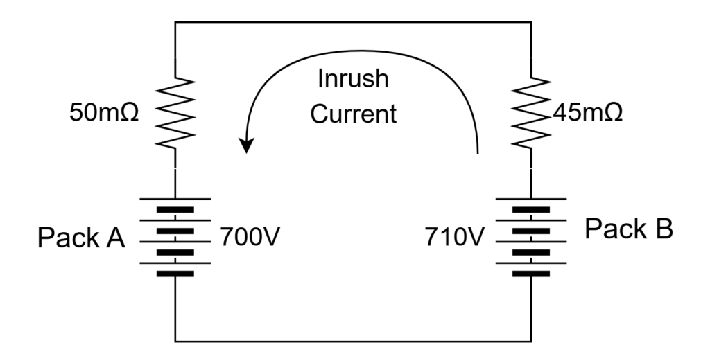
As this inrush current (105.2A) is less than for the manufacturer allowed inrush current (150A), this connection is allowed.
However, if attempting to connect Pack C to Pack A:
- Voltage difference = 725V – 700V = 25V
- Resistance 90 mOhm
- Inrush Current = 25V / 0.090Ω ≈ 277.7A (which exceed the safe limit)
Hence, Pack C would be connected later when voltage differences reduce.
*This same logic is applicable for discharging in reverse order (from Battery with high voltage).
Summary
Parallel battery systems offer scalability for high-energy EVs, but managing them effectively requires sophisticated control strategies. Voltage imbalances, inrush currents, and varying internal resistances pose serious challenges. Through intelligent coordination using the VCU, packs can be safely connected and disconnected based on real-time measurements and estimations. Such control ensures maximum uptime, optimal performance, and longevity of the battery system—an essential requirement for commercial EV applications.
For fleet operators, such intelligent pack-level management translates to improved reliability, reduced maintenance costs, and better return on investment for EV assets.
EV Charging Explained – Everything you need to know about Electric Vehicle Charging